
Cutting equipment and control method thereof

A technology of cutting equipment and cutting machine, applied in metal processing equipment, measuring/indicating equipment, manufacturing tools, etc., can solve the problems of inability to realize circular cutting and sorting of steel plates, low cutting efficiency, and low work efficiency

Pending Publication Date: 2021-01-05
上海气焊机厂有限公司
View PDF0 Cites 0 Cited by
  • Summary
  • Abstract
  • Description
  • Claims
  • Application Information

AI Technical Summary

Problems solved by technology

However, in the process of cutting steel plates, the current gantry-type CNC cutting machines generally use manual methods for sorting and unloading of steel plates, resulting in low work efficiency and the inability to realize circular cutting and sorting of steel plates. The cutting efficiency of the machine is low, and the degree of automation is low; and the sorting and unloading are carried out manually, which is easy to cause personal injury during the work process

Method used


Image

  • Cutting equipment and control method thereof
  • Cutting equipment and control method thereof

Examples


Embodiment 1

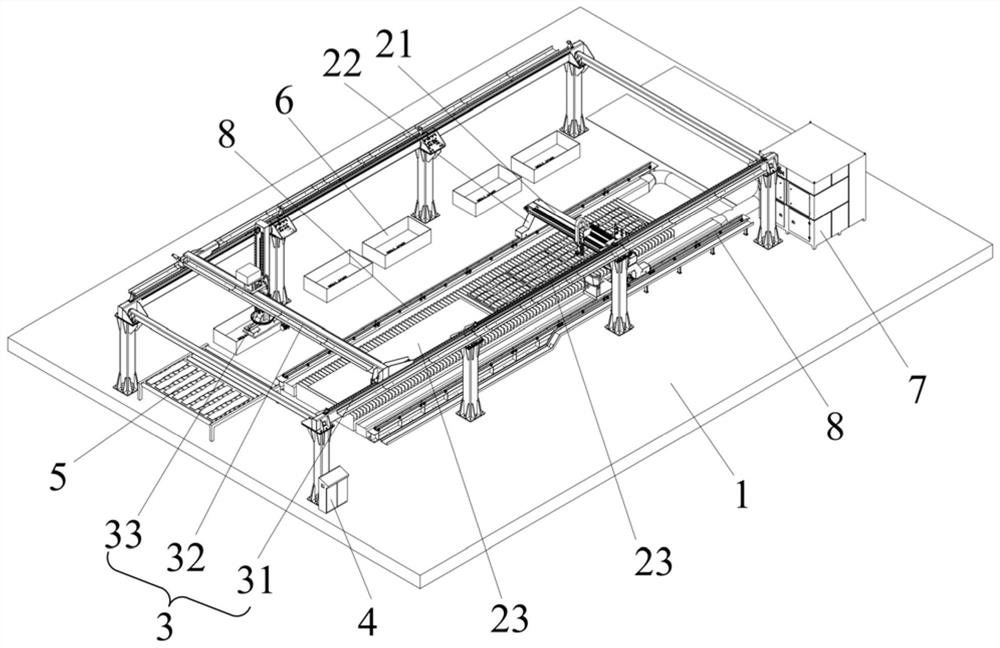
[0044] In this embodiment, a cutting device is proposed. The cutting device is arranged on the bottom plate 1. The cutting device can realize the circular cutting and sorting work of the pieces to be cut, so that the working efficiency of cutting and sorting is high, and the entire cutting device High degree of automation. Specifically, such as figure 1As shown, the cutting equipment includes a cutting system, a truss system 3 and a control system 4 . The cutting system is arranged inside the truss system 3 , and the control system 4 is arranged outside the truss system 3 . Wherein, the cutting system includes a cutting machine 21 and two cutting stations 23 arranged side by side. The cutting machine 21 is slidably arranged on the top of the cutting station 23. The cutting machine 21 can slide relative to the cutting station 23. Positions 23 are provided with sensors for detecting the position of the piece to be cut; the truss system 3 includes a bracket 31 and an adsorption...

Embodiment 2

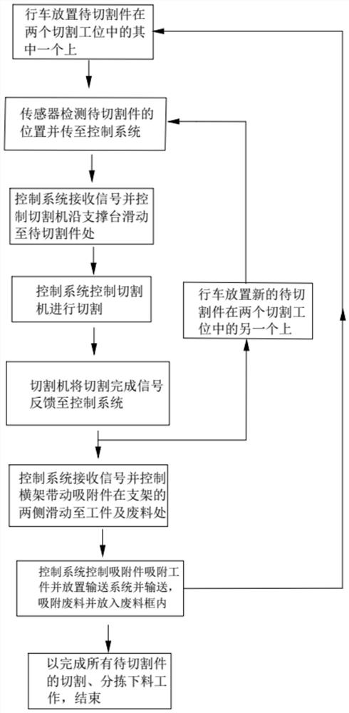
[0059] In this embodiment, a control method based on the cutting device in the first embodiment is proposed, and the control method of the cutting device includes the following steps:

[0060] Place the piece to be cut: place the piece to be cut on one of the two cutting stations 23, the sensor detects the position of the piece to be cut and transmits it to the control system 4;

[0061] Cut the piece to be cut; the control system 4 receives the signal from the sensor, and controls the cutting machine 21 to move to the top of the piece to be cut, and the control system 4 controls the cutting machine 21 to start cutting the piece to be cut to form workpieces and waste materials. Place the piece to be cut on another of the two cutting stations 23 of the piece to be cut;

[0062]Sorting workpieces and waste materials; after the cutting machine 21 completes the cutting, it feeds back the cutting completion signal to the control system 4, and after receiving the signal, the control...


PUM


Abstract

The invention discloses cutting equipment and a control method thereof, and belongs to the technical field of material processing. The cutting equipment comprises a cutting system, a truss system anda control system, wherein the cutting system comprises a cutting machine and two cutting stations arranged in parallel, the cutting machine is arranged at the top ends of the cutting stations in a sliding mode, and the two cutting stations are each provided with a sensor used for detecting the positions of to-be-cut pieces; the truss system comprises a support and an adsorption assembly arranged on the support in a sliding mode, the adsorption assembly is located at the top ends of the cutting stations, and the adsorption assembly is used for adsorbing workpieces and waste materials formed after the to-be-cut pieces are cut; and the sensors are in signal connection with the control system, and the control system is in control connection with the cutting machine and the adsorption assembly.The cutting equipment and the control method thereof have the advantages that cyclic cutting and sorting of the to-be-cut pieces can be achieved, and the cutting equipment has the characteristics ofbeing high in working efficiency and automation degree.

Description

technical field [0001] The invention relates to the technical field of material processing, in particular to a cutting device and a control method thereof. Background technique [0002] The gantry type CNC cutting machine has the characteristics of stable operation, good configuration and high work efficiency, and is widely used in cutting large, medium and small steel plates of various carbon steel, manganese steel and stainless steel metal materials. However, in the process of cutting steel plates, the current gantry-type CNC cutting machines generally use manual methods for sorting and unloading of steel plates, resulting in low work efficiency and the inability to realize circular cutting and sorting of steel plates. The cutting efficiency of the cutting machine is low, and the degree of automation is low; and the sorting and unloading are carried out manually, which may easily cause injuries to personnel during the work process. [0003] In view of the above problems, ...

Claims


Application Information

Patent Timeline
IPC IPC(8): B23D79/00B23Q3/06B23Q7/00B23Q11/00B23Q17/22
CPCB23D79/00B23Q3/06B23Q7/00B23Q11/0046B23Q17/22
Inventor 不公告发明人
Owner 上海气焊机厂有限公司
Learn More