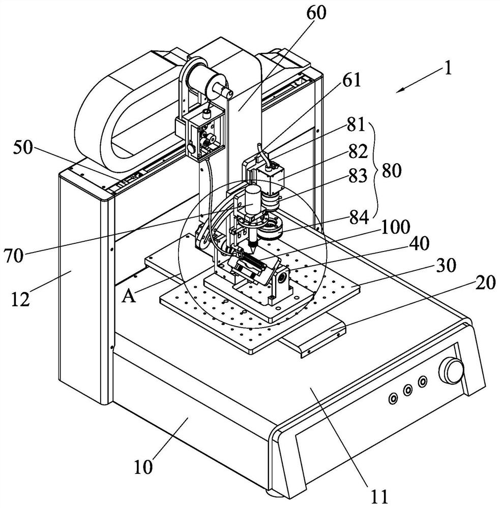
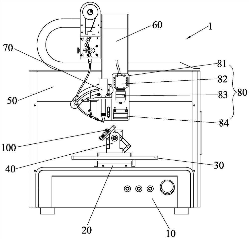
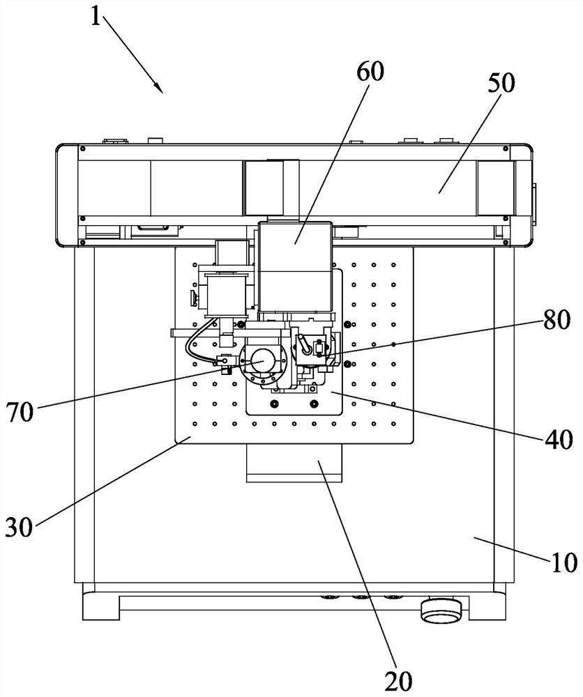
Table type soldering iron tin soldering equipment

A soldering iron and soldering tin technology, applied in the field of desktop soldering iron soldering equipment, can solve the problems of high technical level of employees, difficult manual operation, decrease in hardness of solder joints, etc., to improve soldering effect, low equipment cost, and ensure solder quality Effect

Pending Publication Date: 2021-01-05
厦门柔性电子研究院有限公司 +2
View PDF0 Cites 5 Cited by
  • Summary
  • Abstract
  • Description
  • Claims
  • Application Information

AI Technical Summary

Problems solved by technology

The main purpose of removing the gold-plated layer on the inner surface of the solder cup is to prevent the fusion of the solder and the gold-plated layer on the solder cup to form "gold brittleness", which will reduce the hardness of the solder joints and cause severe fractures
At present, the gold-plated layer on the inner surface of the solder cup of the soldered connector is mainly removed by manual welding with a soldering iron and suction welding. The solder cup of the terminal is small and deep, and manual operation is difficult and time-consuming. It requires a high level of technical staff. Moreover, the yield rate is low and the production efficiency is low. For this reason, the present invention conducts research, optimization and improvement on the technical transformation of the soldering step of this type of product and its automation equipment.

Method used


Image

  • Table type soldering iron tin soldering equipment
  • Table type soldering iron tin soldering equipment
  • Table type soldering iron tin soldering equipment

Examples


Embodiment Construction

[0054] In order to further explain the technical solution of the present invention, the present invention will be described in detail below through specific examples.

[0055] In describing the present invention, it should be understood that the terms "center", "longitudinal", "transverse", "length", "width", "thickness", "upper", "lower", "front", " Orientation or position indicated by "back", "left", "right", "vertical", "horizontal", "top", "bottom", "inner", "outer", "clockwise", "counterclockwise", etc. The relationship is based on the orientation or positional relationship shown in the drawings, and is only for the convenience of describing the present invention and simplifying the description, rather than indicating or implying that the referred device or element must have a specific orientation, be constructed and operated in a specific orientation, therefore It should not be construed as a limitation of the present invention.

[0056] In addition, the terms "first" a...


PUM


Abstract

The invention discloses table type soldering iron tin soldering equipment. The equipment comprises a machine box, a Y-axis linear module, a movable carrying table, a positioning and rotating mechanism, an X-axis linear module, a Z-axis linear module, a soldering iron tin soldering assembly and a camera module, the Y-axis linear module is arranged on a workbench of the machine box, the movable carrying table is arranged on the Y-axis linear module and can move forwards and backwards along with the Y-axis linear module, the positioning and rotating mechanism is arranged on the movable carrying table, the X-axis linear module is arranged above the workbench, the Z-axis linear module is arranged on the X-axis linear module, and the soldering iron soldering tin assembly and the camera module are arranged on the Z-axis linear module. A convenient table type structure is adopted, the equipment cost is low, and the placement position can be flexibly adjusted according to the layout of a plant;and a soldering iron soldering process is adopted, the process is mature, soldering iron use and maintenance cost is low, and tin soldering quality of products can be well guaranteed by replacing soldering iron according to the service life of the soldering iron.

Description

technical field [0001] The invention relates to the technical field of soldering processing of electronic products, in particular to a desktop soldering iron soldering equipment. Background technique [0002] During the installation process of electronic products, soldering process is required, and some electronic products need to use soldering and tin absorption process to remove the gold plating layer on the surface of the product. The gold-plated layer on the surface needs to be removed before the wire is soldered. The main steps are soldering and tin absorption. The solder is melted in the empty solder cup of the terminal through the soldering process, so that the gold-plated layer on the surface of the solder cup is melted in the solder, and then through the tin suction. The process melts the solder in the empty solder cup again and uses a tin suction tool to suck out the solder and clean it up, so as to remove the gold-plated layer on the inner surface of the solder cu...

Claims


Application Information

Patent Timeline
Patent Type & Authority Applications(China)
IPC IPC(8): B23K3/00B23K3/06B23K3/08
CPCB23K3/00B23K3/063B23K3/08
Inventor 续振林徐隐崽张金发李谦赵继伟陈妙芳
Owner 厦门柔性电子研究院有限公司
Why Eureka
Try Eureka