Efficient automatic spot welding device for upper longitudinal beam support

An automatic spot welding and longitudinal beam technology, applied in auxiliary devices, welding equipment, welding equipment, etc., can solve the problems of safety and quality hidden dangers, high labor intensity of workers, and high cost of working hours, so as to improve the market competitiveness of enterprises and reduce work-related injuries , easy maintenance effect

Pending Publication Date: 2021-01-05
ZHEJIANG CHANGHUA AUTO PARTS
View PDF4 Cites 1 Cited by
  • Summary
  • Abstract
  • Description
  • Claims
  • Application Information

AI Technical Summary

Problems solved by technology

In the processing of fasteners, during the spot welding process of the upper longitudinal beam, it is necessary to manually put the upper longitudinal beam bracket, and then manually put the spot welding bolts into the holes of the upper longitudinal beam bracket and start the spot welding equipment for spot welding; this This kind of work is done manually, resulting in high labor intensity, low efficiency, and certain safety and quality risks.
[0003] The spot welding process of the prior art uses manual assembly and spot welding. In the spot welding operation, there are occasional spot welding of defective products, which also requires relatively skilled workers to operate the spot welding, and the cost of man-hours is also high.

Method used


Image

  • Efficient automatic spot welding device for upper longitudinal beam support
  • Efficient automatic spot welding device for upper longitudinal beam support
  • Efficient automatic spot welding device for upper longitudinal beam support

Examples


Embodiment Construction

[0029] Several preferred embodiments of the present invention will be described in detail below with reference to the accompanying drawings, but the present invention is not limited to these embodiments. The present invention covers any alternatives, modifications, equivalent methods and schemes made on the spirit and scope of the present invention. In order to provide the public with a thorough understanding of the present invention, specific details are set forth in the following preferred embodiments of the present invention, but those skilled in the art can fully understand the present invention without the description of these details. In addition, well-known methods, procedures, processes, components, etc. have not been described in detail in order to avoid unnecessary confusion to the essence of the present invention.

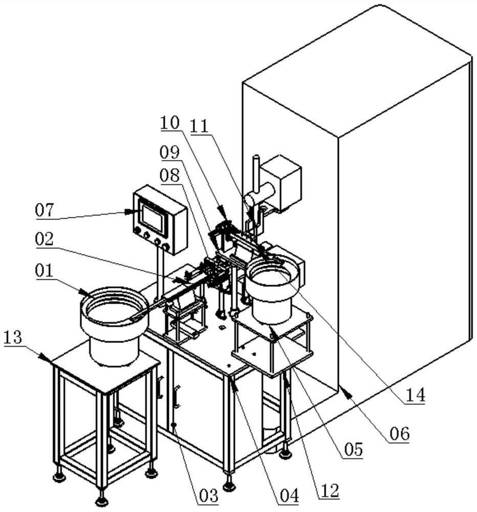
[0030] Please refer to figure 1 An efficient automatic spot welding device for upper longitudinal beam brackets of the present application is used for ...


PUM


Abstract

The invention provides an efficient automatic spot welding device for an upper longitudinal beam support. The efficient automatic spot welding device comprises an upper longitudinal beam support turnover device. The upper longitudinal beam support turnover device turns over the upper longitudinal beam support by 180 degrees. The upper longitudinal beam support turnover device comprises a limitingplate, a fixed rack, a turnover connecting block, a turnover sliding block, a turnover gear, a clamping block and a clamping air cylinder. The turnover connecting block is an L-shaped body. One end ofthe turnover connecting block is connected with a feeding air cylinder, and the other end of the turnover connecting block is arranged on one side of the limiting plate and connected with the turnover sliding block. The fixed rack is arranged on the other side of the limiting plate. The turnover gear is arranged above the fixed rack. A center shaft of the turnover gear penetrates a through hole of the turnover sliding block and then is fixedly connected with the clamping block. The clamping air cylinder is arranged on the clamping block. The efficient automatic spot welding device is reliablein structure, convenient to use, easy to maintain and high in universality, safety production is achieved, and the market competitiveness of enterprises is improved.

Description

technical field [0001] The invention relates to a spot welding device, in particular to a high-precision and high-efficiency automatic spot welding device for an upper longitudinal beam bracket used in automobiles. Background technique [0002] With the development of science and technology, the advancement of technology, the rapid change of automobile products, also put forward higher requirements for fastener products, and auto parts are an important field for my country's automobile industry to participate in globalization. In the processing of fasteners, during the spot welding process of the upper longitudinal beam, it is necessary to manually put the upper longitudinal beam bracket, and then manually put the spot welding bolts into the holes of the upper longitudinal beam bracket and start the spot welding equipment for spot welding; this This kind of work is done manually, resulting in high labor intensity, low efficiency, and certain safety and quality hidden dangers...

Claims


Application Information

Patent Timeline
Patent Type & Authority Applications(China)
IPC IPC(8): B23K11/00B23K11/11B23K11/36B23K37/047
CPCB23K11/115B23K11/36B23K37/047B23K11/002
Inventor 王长土
Owner ZHEJIANG CHANGHUA AUTO PARTS
Why Eureka
Try Eureka