Cylindrical shaft rod piece inwards-concave arc ring groove machining device and using method thereof

A cylindrical shaft and processing device technology, applied in positioning devices, feeding devices, metal processing and other directions, can solve the problems of low product qualification rate, unfavorable production efficiency, high labor intensity, etc., to improve product qualification rate and reduce product processing. Difficulty, improve work efficiency

Active Publication Date: 2021-01-05
吴子昂
View PDF7 Cites 7 Cited by
  • Summary
  • Abstract
  • Description
  • Claims
  • Application Information

AI Technical Summary

Problems solved by technology

[0002] When machining the inner concave circular arc ring groove of the cylindrical shaft, the operator usually needs the operator to fix the cylindrical shaft blank on the chuck of the machine tool, and during processing, the operating tool is fed in both the horizontal and vertical directions. Cutting process, and remove the finished workpiece from the chuck of the machine tool after the machining is completed, so the labor intensity is high, and the processing is difficult because it requires a high degree of concentration and high machine description requirements when controlling the feed. The product pass rate is low, which is not conducive to improving production efficiency

Method used


Image

  • Cylindrical shaft rod piece inwards-concave arc ring groove machining device and using method thereof
  • Cylindrical shaft rod piece inwards-concave arc ring groove machining device and using method thereof
  • Cylindrical shaft rod piece inwards-concave arc ring groove machining device and using method thereof

Examples


Embodiment Construction

[0030]The technical solutions in the embodiments of the present invention will be clearly and completely described below in conjunction with the accompanying drawings in the embodiments of the present invention. Obviously, the described embodiments are only a part of the embodiments of the present invention, rather than all the embodiments. Based on the embodiments of the present invention, all other embodiments obtained by those of ordinary skill in the art without creative work shall fall within the protection scope of the present invention.

[0031]SeeFigure 1 to Figure 8, The present invention provides a technical solution:

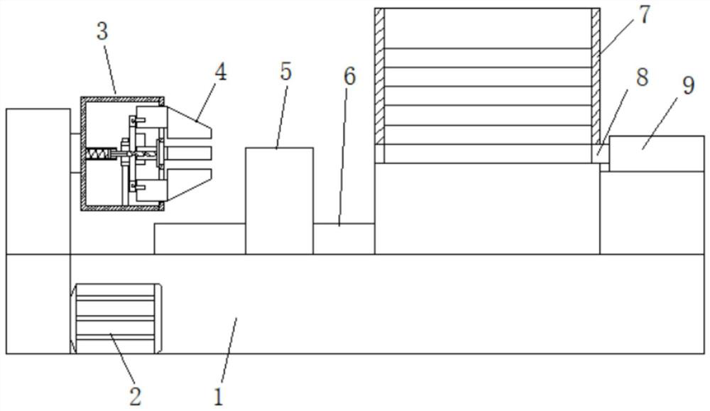
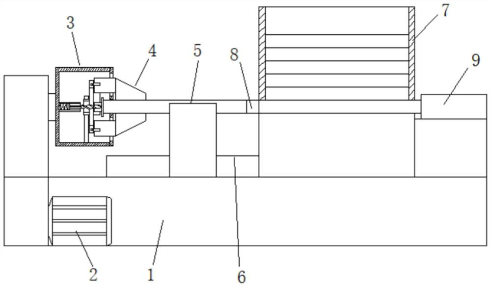
[0032]A processing device for concave circular arc ring grooves of cylindrical shafts, comprising a machine base 1, a right motor 2 fixed on the machine base 1, a clamping mechanism 3 for clamping and fixing a workpiece, a motor 2 and a clamping mechanism 3 Transmission connection, the machine bed 1 is provided with a cutter 32 for cutting the workpiece, and the ...


PUM


Abstract

The invention relates to the field of shaft rod piece groove machining equipment, in particular to a cylindrical shaft rod piece inwards-concave arc ring groove machining device and a using method thereof. A cutter used for cutting a workpiece is arranged on a machine tool base, a feeding mechanism used for automatically conveying the workpiece is arranged on the machine tool base, the feeding mechanism drives a clamping mechanism to clamp and fix the workpiece by pushing the workpiece, a cutter feeding mechanism is arranged on the machine tool base, the cutter is fixed on the cutter feeding mechanism, and the cutter feeding mechanism drives the cutter to cut the workpiece. A material receiving box used for receiving the machined and formed workpiece is fixed to the machine tool base. According to the cylindrical shaft rod piece inwards-concave arc ring groove machining device and the using method thereof, in the whole machining process, no manpower is needed for installation and taking-out work of the workpiece, the work efficiency is improved, no personal error is generated, the product yield is increased, and the product machining difficulty is lowered.

Description

Technical field[0001]The invention relates to the field of processing equipment for shaft grooves, in particular to a processing device for concave circular arc ring grooves in cylindrical shafts and a use method thereof.Background technique[0002]When machining the concave arc ring groove of the cylindrical shaft, it is usually necessary for the operator to fix the cylindrical shaft blank on the chuck of the machine tool, and during processing, the operating tool feeds in both the horizontal and vertical directions Cutting process, and removing the finished workpiece from the chuck of the machine tool after the machining is completed, so the labor intensity is high, and because of the high concentration of energy and high mechanical requirements when controlling the feed, the processing is difficult. The low product qualification rate is not conducive to improving production efficiency.[0003]In view of this, we propose a concave arc ring groove processing device for cylindrical shaf...

Claims


Application Information

Patent Timeline
Patent Type & Authority Applications(China)
IPC IPC(8): B23Q7/00B23Q3/06B23Q5/22
CPCB23Q3/06B23Q3/062B23Q3/064B23Q5/22B23Q7/00
Inventor 吴子昂
Owner 吴子昂
Why Eureka
Try Eureka