
Unmanned aerial vehicle long-distance power supply method

A power supply method and unmanned aerial vehicle technology, applied in the field of unmanned aerial vehicles, can solve the problems that the charging device cannot be applied to various models, the laser incident angle cannot be guaranteed, and the charging efficiency is reduced, so as to achieve fast and efficient charging, effective heat dissipation, The effect of efficient use

Active Publication Date: 2021-01-05
军事科学院系统工程研究院军事新能源技术研究所
View PDF10 Cites 5 Cited by
  • Summary
  • Abstract
  • Description
  • Claims
  • Application Information

AI Technical Summary

Problems solved by technology

At present, the battery of drones mainly uses chargers for wired charging. The disadvantage is that the cruising range is short, and the battery needs to be disassembled. At the same time, the voltage platform and charging interface of different drones are different, resulting in a high degree of personnel participation. , low protection efficiency
[0004] At present, an important factor limiting the development of laser wireless power supply technology is the heat dissipation of the battery board. Excessive temperature rise of photovoltaic cells has a great impact on energy transfer efficiency. Existing heat dissipation methods cannot effectively solve the problem of low energy transfer efficiency caused by high temperature. question
Another important factor limiting the development of laser wireless power supply technology is the problem of the incident angle between the battery board and the laser. During the charging process, the incident angle of the laser cannot be guaranteed to be vertical, which reduces the charging efficiency.
There is also the problem that the charging device cannot be applied to multiple models in the prior art

Method used


Image

  • Unmanned aerial vehicle long-distance power supply method
  • Unmanned aerial vehicle long-distance power supply method
  • Unmanned aerial vehicle long-distance power supply method

Examples


Embodiment Construction

[0028] The following will clearly and completely describe the technical solutions in the embodiments of the present specification in conjunction with the accompanying drawings in the embodiments of the present specification. Obviously, the described embodiments are only some embodiments of the present invention, not all embodiments. Based on the embodiments of the present invention, all other embodiments obtained by persons of ordinary skill in the art without making creative efforts belong to the protection scope of the present invention.

[0029] It should be noted that the terms "include" and "have" in the embodiments of this specification and the drawings, as well as any variations thereof, are intended to cover non-exclusive inclusion. For example, a process, method, system, product or device comprising a series of steps or units is not limited to the listed steps or units, but optionally also includes unlisted steps or units, or optionally further includes For other step...


PUM


Abstract

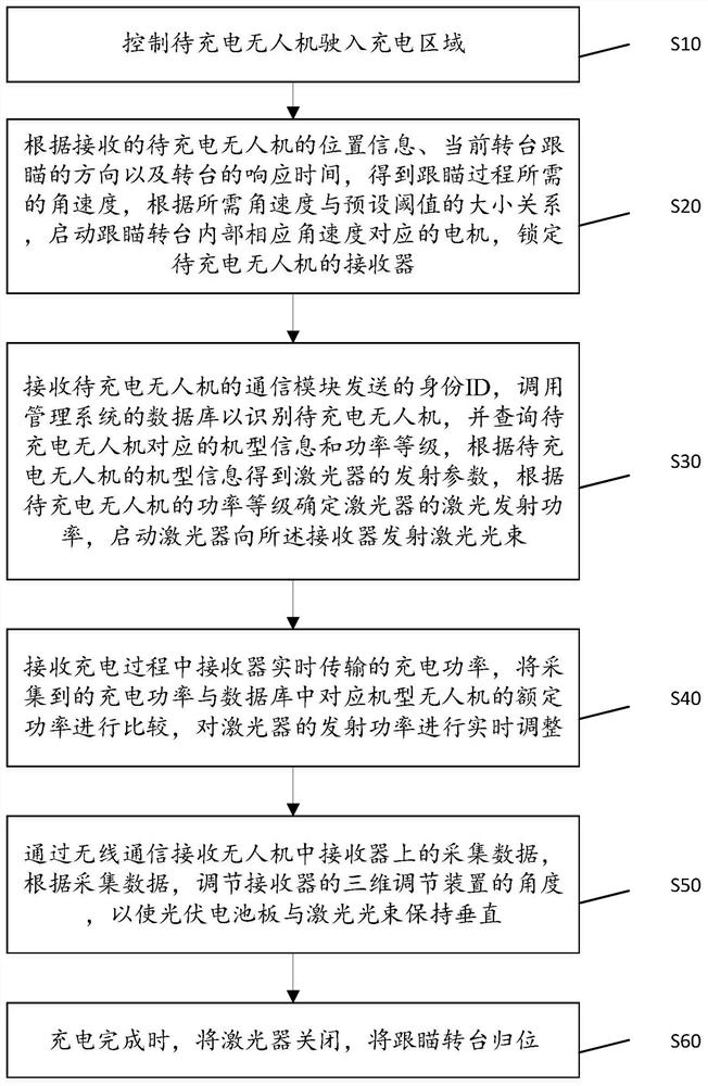
The invention discloses an unmanned aerial vehicle long-distance power supply method which is suitable for being executed on a controller of a wireless power supply device. The method comprises the steps of S10 controlling an unmanned aerial vehicle to be charged to drive into a charging area; S20 according to the received position information of the to-be-charged unmanned aerial vehicle, the tracking and pointing direction of a rotary table and the response time, starting a motor corresponding to the tracking and pointing rotary table, and locking a receiver of the to-be-charged unmanned aerial vehicle; S30 calling a database to identify the to-be-charged unmanned aerial vehicle, querying the corresponding information of the to-be-charged unmanned aerial vehicle, determining the laser emission power of a laser according to the corresponding information, and starting the laser to emit a laser beam to the receiver; S40 receiving the charging power transmitted by the receiver in real time in the charging process, comparing the received data with the rated power of the model in the database, and adjusting the transmitting power of the laser in real time; S50 receiving collecting dataof the unmanned aerial vehicle through wireless communication, and adjusting the angle of a three-dimensional adjusting device of the receiver according to the collecting data; and S60 after chargingis completed, turning off the laser, and enabling the rotary table to return to the original position.

Description

technical field [0001] The present invention relates to the technical field of unmanned aerial vehicles, in particular, to a remote power supply method for unmanned aerial vehicles. Background technique [0002] Because of its convenient use and good economical advantages, UAVs can replace traditional operating methods in some high-risk and difficult tasks, and have a wide range of applications in intelligent patrol inspection, aerial photography mapping, forest fire prevention and other fields. However, UAVs lack the long-endurance operation capability. In order to ensure the battery life and voyage, it is necessary to establish a power supply device to complete the long-distance, efficient and intelligent power transmission of UAVs. At present, the battery of drones mainly uses chargers for wired charging. The disadvantage is that the cruising range is short, and the battery needs to be disassembled. At the same time, the voltage platform and charging interface of differen...

Claims


Application Information

Patent Timeline
Patent Type & Authority Applications(China)
IPC IPC(8): B60L53/10B60L53/65B60L53/37H02J7/00H02J50/30H02J50/80H02J50/90B64C39/02
CPCB60L53/10B60L53/65B60L53/37H02J7/0047H02J7/0029H02J50/30H02J50/80H02J50/90B64C39/02B60L2200/10Y02T10/70Y02T10/7072Y02T90/12Y02T90/14Y02T90/16Y02T90/167Y04S30/14
Inventor 王长富徐万里鲁长波王旭东刘盼盼周友杰李施展安高军陈今茂吕立通徐曦萌孙彦丽
Owner 军事科学院系统工程研究院军事新能源技术研究所
Learn More