Ignition plug with pre-chamber and device for flushing pre-chamber

A technology of ignition plug and pre-combustion chamber, which is applied in the field of ignition plug to avoid overheating

Pending Publication Date: 2021-01-05
FORD GLOBAL TECH LLC
View PDF3 Cites 2 Cited by
  • Summary
  • Abstract
  • Description
  • Claims
  • Application Information

AI Technical Summary

Problems solved by technology

[0002] Glow plugs with pre-chambers improve combustion under certain conditions, but there are certain risks
Here, a challenge is to thoroughly flush the hot combustion gases in the pre-chamber, especially in the area between the separator and the casing in the upper area of ​​the pre-chamber

Method used


Image

  • Ignition plug with pre-chamber and device for flushing pre-chamber
  • Ignition plug with pre-chamber and device for flushing pre-chamber
  • Ignition plug with pre-chamber and device for flushing pre-chamber

Examples


Embodiment Construction

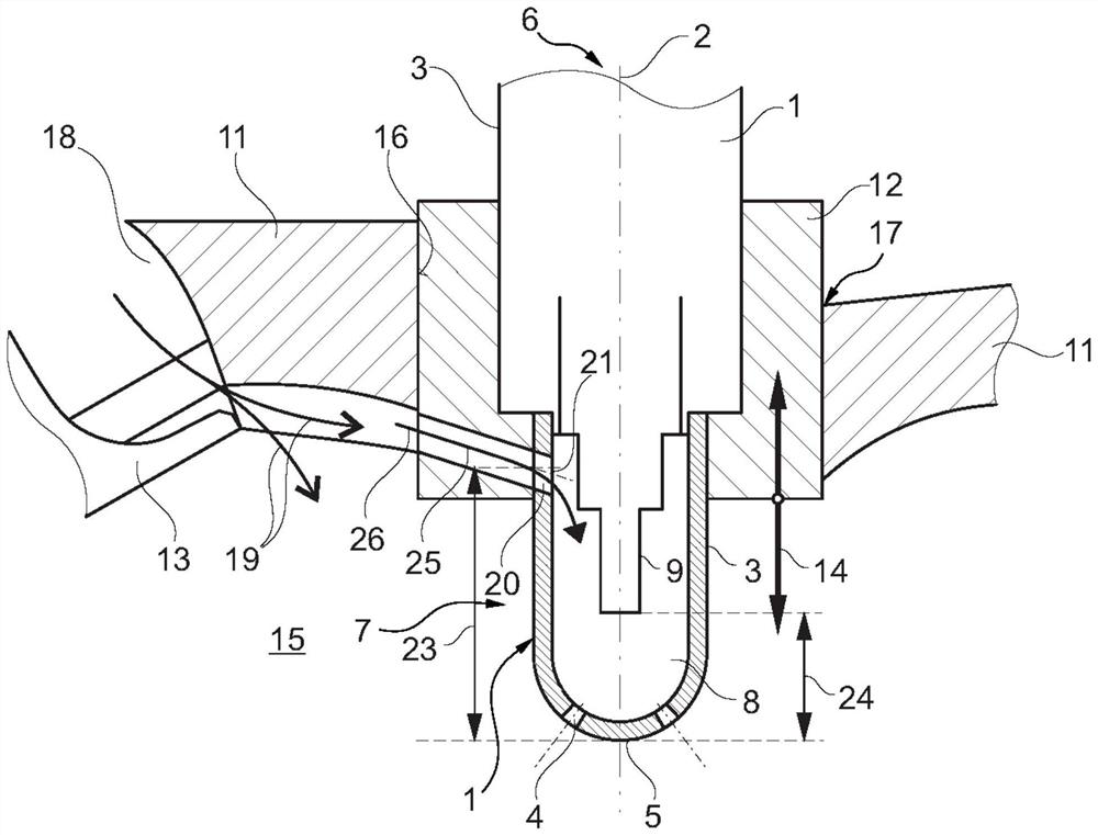
[0028] figure 1 A detail of a cylinder head 11 according to the invention with a glow plug 1 according to the invention is shown schematically in partial section. The cylinder head 11 comprises an opening 17 in which the ignition plug 1 is arranged and a further opening 18 with an inlet valve 13 . The opening 17 has an inner surface 16 .

[0029] Glow plug 1 has a longitudinal axis 2 . Glow plug 1 also has an outer wall 3 . The glow plug further comprises, in the longitudinal direction 2 , a combustion chamber-side end 5 and a combustion chamber-opposite end 6 , which in figure 1 is not explicitly shown. The outer wall 3 includes a combustion chamber-side region 7 which is configured to be arranged in the combustion chamber 15 or to protrude into the combustion chamber 15 .

[0030] A prechamber 8 is arranged at the combustion chamber-side end 5 . At least one ignition electrode 9 is arranged in the pre-chamber 8 . Furthermore, the pre-chamber 8 comprises at least one c...


PUM


Abstract

Described is an ignition plug (1) comprising an outer wall (3) comprising a combustion chamber-side region (7) configured to be arranged in a combustion chamber (15), a longitudinal axis (2), a combustion chamber-side end (5) in the longitudinal direction and a combustion chamber counter-end (6), at least one pre-combustion chamber (8) being arranged at the combustion chamber-side end (5), and thepre-combustion chamber (8) has at least one combustion chamber-side opening (4) for conducting the mixture that has been ignited in the pre-combustion chamber into the combustion chamber (15). The outer wall (3) is at least partially surrounded in the circumferential direction by a support (12), at least one flow channel (20, 25) for flushing the pre-chamber extends through the support (12) and the outer wall (8) in the region of the pre-chamber (8), the at least one flow channel fluidically connecting the pre-chamber (8) to the combustion chamber-side region (7), wherein the flow channel (20, 25) for flushing the pre-chamber is configured to be opened and closed by means of a displacement of the bracket (12) relative to the cylinder head (11) in an installed state within the cylinder head (11).

Description

technical field [0001] The invention relates to a glow plug with a prechamber, a method for operating a glow plug with a prechamber, an internal combustion engine and a vehicle, such as a motor vehicle. Background technique [0002] Glow plugs with pre-chambers improve combustion under certain conditions, but there are certain risks. A challenge here is to thoroughly flush out the hot combustion gases in the pre-chamber, especially in the area between the separator and the casing in the upper area of ​​the pre-chamber. Without adequate flushing, premature ignition can occur in these areas. Furthermore, the ignition electrodes arranged in the pre-chamber are difficult to cool, in particular because they are surrounded by hot combustion gases most of the time. [0003] Document DE 10 2005 017 186 A1 describes a method for flushing the pre-chamber of a glow plug, as far as possible and including flushing into the region of the ignition electrode. In this case, the residual g...

Claims


Application Information

Patent Timeline
Patent Type & Authority Applications(China)
IPC IPC(8): F02B19/12F02F1/24H01T13/02H01T13/06
CPCF02B19/12F02F1/242H01T13/02H01T13/06F02B19/18Y02T10/12
Inventor F·克拉默O·贝克迈尔H·H·鲁兰T·洛伦茨A·布罗伊尔M·科霍斯罗维
Owner FORD GLOBAL TECH LLC
Why Eureka
Try Eureka