
Pixel circuit

A pixel circuit and buffer circuit technology, applied in the field of pixel circuits, can solve the problems of increasing voltage difference, signal swing limitation, signal swing limitation, etc., and achieve the effect of improving overall performance and increasing voltage swing

Active Publication Date: 2021-01-05
HIMAX IMAGING LIMITED
View PDF14 Cites 0 Cited by
  • Summary
  • Abstract
  • Description
  • Claims
  • Application Information

AI Technical Summary

Problems solved by technology

There will be a voltage difference between the input signal and the output signal of the source follower, so that the signal swing of these readout signals is limited
In addition, the threshold voltage of the transistor in the source follower will change due to the body effect, thereby increasing the voltage difference between the input signal and the output signal of the source follower, so the signal of these readout signals The swing will be further restricted

Method used


Image

  • Pixel circuit
  • Pixel circuit

Examples


Embodiment Construction

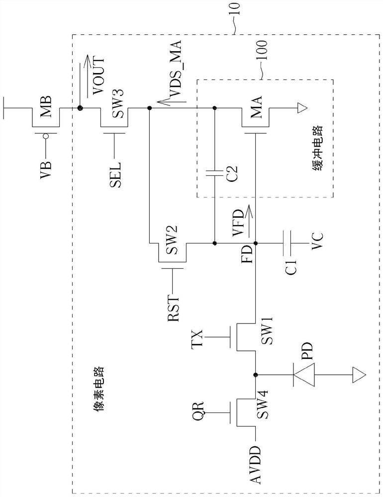
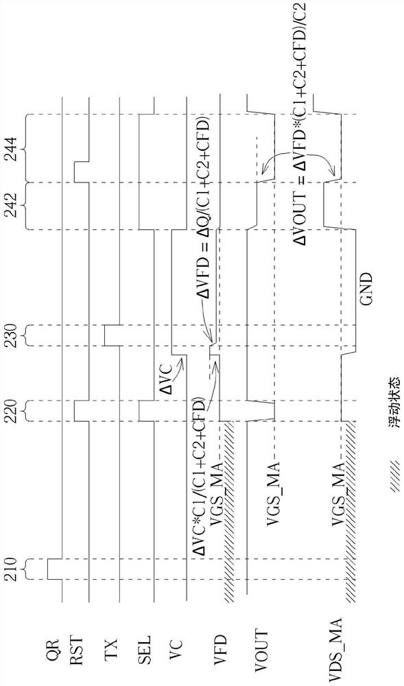
[0028] figure 1 It is a schematic diagram of a pixel circuit 10 according to an embodiment of the present invention. Such as figure 1 As shown, the pixel circuit 10 may include a photodiode (photodiode) PD, a buffer circuit 100 , a capacitor C1 , a switch SW1 , a switch SW2 and a switch SW3 . The photodiode PD is used to accumulate electric charge (such as electrons) in response to incident light to generate a photodiode signal, and the buffer circuit 100 is used to output at least one readout signal, wherein the input terminal of the buffer circuit 100 is coupled to a specific node (such as a floating A floating diffusion node) such as node FD, and the signal on node FD is represented by signal VFD. The capacitor C1 is coupled between the control voltage terminal (controlled by the signal VC) of the pixel circuit 10 and the node FD, the switch SW1 is coupled between the photodiode PD and the node FD, and the switch SW2 is coupled to the input terminal of the buffer circuit ...


PUM


Abstract

A pixel circuit is provided, where the pixel circuit comprises a photodiode, a buffer circuit, a first capacitor, a first switch, a second switch and a third switch. The photodiode is configured to accumulate charges in response to incident radiation, to generate a photodiode signal. The buffer circuit is configured to output at least one read-out signal, wherein an input terminal of the buffer circuit is coupled to a specific node. The first capacitor is coupled between a control voltage terminal of the pixel circuit and the specific node. The first switch is coupled between the photodiode and the specific node. The second switch is coupled between the input terminal of the buffer circuit and an output terminal of the buffer circuit. The third switch is coupled between the output terminalof the buffer circuit and a read-out terminal of the pixel circuit.

Description

technical field [0001] The present invention relates to an electronic circuit, in particular to a pixel circuit applicable to a Complementary Metal-Oxide-Semiconductor (CMOS) image sensor. Background technique [0002] In the related art, a source follower can be used to output the readout signal of the pixel circuit. There is a voltage difference between the input signal and the output signal of the source follower, so that the signal swing of these readout signals is limited. In addition, the threshold voltage of the transistor in the source follower will change due to the body effect, thereby increasing the voltage difference between the input signal and the output signal of the source follower, so the signal of these readout signals The swing will be further restricted. Therefore, a novel pixel circuit architecture is needed to solve the above problems. Contents of the invention [0003] The purpose of the present invention is to provide a pixel circuit to solve the...

Claims


Application Information

Patent Timeline
Patent Type & Authority Applications(China)
IPC IPC(8): H04N5/374H04N5/378H01L27/146
CPCH01L27/14643H04N25/76H04N25/77H04N25/75
Inventor 欧翰硕
Owner HIMAX IMAGING LIMITED
Learn More