
Full-automatic high-temperature-melt release mechanism and control method thereof

A technology of high temperature melting and releasing mechanism, applied in chemical instruments and methods, laboratory utensils, reagent containers, etc., can solve the problems of damage to the melting furnace, the valve cannot be moved, and the pressure is not adjustable, so as to meet the requirements of reducing temperature resistance. , Excellent thermal shock resistance, avoid high temperature failure effect

Active Publication Date: 2021-01-08
NUCLEAR POWER INSTITUTE OF CHINA
View PDF24 Cites 1 Cited by
  • Summary
  • Abstract
  • Description
  • Claims
  • Application Information

AI Technical Summary

Problems solved by technology

During the transfer process, if the high-temperature molten material is in contact with pipes and valves for a long time, it will cause problems such as high-temperature yield of steel components, failure of pressure-bearing seals, and inability of valves to operate; at the same time, high-temperature molten material contacts steel components. When the wall surface is closed, a hard shell will be formed to cover the wall surface after solidification, which will greatly affect the difficulty of movement and pressure sealing at the valve.
[0003] In the face of these technical difficulties, the current experimental techniques are divided into two categories: one is to choose to reduce the pressure in the bottom pressure vessel to normal pressure, without setting a release mechanism, and the high-temperature melt is directly released from the melting furnace into the bottom experimental vessel. This design does reduce the difficulty of release, but it makes the system pressure conditions of the bottom experimental vessel unable to simulate the actual accident conditions well, and does not have the function of pressure adjustment; the other is to choose to put the melting furnace into the In the pressure vessel, when the melt is released, the upper and lower pressure vessels are connected, and the time and space for the melt to contact the release mechanism are shortened as much as possible. However, this design allows the steam and explosion shock waves generated in the bottom vessel to spread to the top vessel. Interference and damage to electrical equipment such as melting furnaces in pressure vessels

Method used


Image

  • Full-automatic high-temperature-melt release mechanism and control method thereof

Examples


Embodiment 1

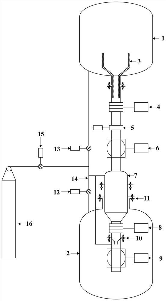
[0046] In view of the background of the difficulty in transferring high-temperature molten matter from a low-pressure environment to a high-pressure environment and the inadequacy of existing experimental techniques to deal with such problems, this embodiment proposes a fully automatic release mechanism for high-temperature molten matter. A temporary storage container is set between the atmospheric pressure container of the top smelting furnace and the bottom experimental container, and the transfer of the melt from the low pressure space to the high pressure space is realized by means of two-stage transfer.

[0047] In this embodiment, the isolation valves placed upstream and downstream of the temporary storage container are separated by a pair of valves to block the high-temperature molten material and to separate the pressure sealing function; the top valve adopts the valve body structure of the gate valve to block the molten material. The valve body is made of steel core wr...

Embodiment 2

[0059] This embodiment proposes a control method for the automatic release mechanism of the high-temperature molten material as proposed in the above-mentioned embodiment 1. This embodiment takes the experimental research of releasing the high-temperature molten material into a pressure vessel with a system pressure of 2 MPa in the form of a jet as an example. To describe, the specific process is as follows:

[0060] Close the melt release valve 8 downstream of the temporary storage container 7, the downstream main sealing valve 9, and the first electric pressure balance valve 12 on the pressure balance pipeline between the temporary storage container 7 and the bottom high-pressure container 2, and fill the bottom high-pressure container 2 The pressure reaches 2MPa;

[0061] Open the protective gate valve 4 upstream of the temporary storage container 7, the upstream sealing valve 6, and the second electric pressure balance valve 13 on the pressure balance line between the temp...


PUM


Abstract

The invention discloses a full-automatic high-temperature-melt release mechanism and a control method thereof. The release mechanism comprises a temporary storage container, wherein the upstream portion of the temporary storage container is connected with a low-pressure container loaded with a smelting furnace through an upstream release pipeline; a protective gate valve and an upstream main sealing valve are sequentially arranged on the portion, from the low-pressure container to the upstream release pipeline of the temporary storage container, of the temporary storage container; a downstreamrelease pipeline is arranged on the downstream portion of the temporary storage container, a melt release valve and a downstream main sealing valve are arranged on the downstream release pipeline, the melt release valve is arranged on the side close to the temporary storage container, and the downstream main sealing valve is arranged on the side away from the temporary storage container; the temporary storage container and downstream devices thereof are arranged in a bottom high-pressure container; and the temporary storage container separately communicates with the low-pressure container, the bottom high-pressure container and a pressure source through pressure balance pipelines. The problem that high-temperature melt is difficult to transfer from a low-pressure environment to a high-pressure environment is solved.

Description

technical field [0001] The invention belongs to the technical field of mechanical automation, and in particular relates to a fully automatic release mechanism for high-temperature molten matter and a control method thereof. Background technique [0002] In the study of the mechanism of severe accidents of nuclear reactors, when conducting experiments on the interaction between core melt and coolant, it is necessary to release high-temperature melt (≥1000°C) from an atmospheric melting furnace into a water pool in a pressure vessel for testing. During the transfer process, if the high-temperature molten material is in contact with pipes and valves for a long time, it will cause problems such as high-temperature yield of steel components, failure of pressure-bearing seals, and inability of valves to operate; at the same time, high-temperature molten material contacts steel components. When it is on the wall, it will form a hard shell to cover the wall after solidification, whi...

Claims


Application Information

Patent Timeline
IPC IPC(8): B01L3/00
CPCB01L3/52B01L3/561B01L3/5635
Inventor 杨生兴宫厚军胡钰文昝元锋李勇杨祖毛李朋洲
Owner NUCLEAR POWER INSTITUTE OF CHINA
Learn More