
Eureka
For R&D, Eureka makes reading and utilizing patents & technical documents easy.
Eureka AIR
Designed for self-driven R&D workflows. Generate viable solutions, solve complex R&D challenges, empower your innovation with AI.

Eureka Materials
Designed for material experts only. Revolutionize your material R&D, from search, analyze, to developing new materials.

TechResearch
Generate reliable direction feasibility study reports for your R&D in just a few steps.

TechSeek
Discover and master advanced knowledge NOW. Basics, ideas, possibilities, all at once.

TechMind
As an expert in R&D Theories, TechMind can generates customized viable solutions instantly.

TechRisk
Analyze your overall solution with one click, know your potential R&D risks in advance.

TechMonitor
Get weekly tech updates, stay abreast of the latest tech innovations and key insights.
Electric spark machining equipment
A processing equipment and EDM technology, which is applied in the field of EDM equipment, can solve the problems of large differences in equipment use experience, non-adjustable height of EDM equipment, and inconvenient adjustment, achieving simple structure, good user experience, and wide applicability Effect
- Summary
- Abstract
- Description
- Claims
- Application Information
AI Technical Summary
Problems solved by technology
Method used
Image


Examples
Embodiment 1
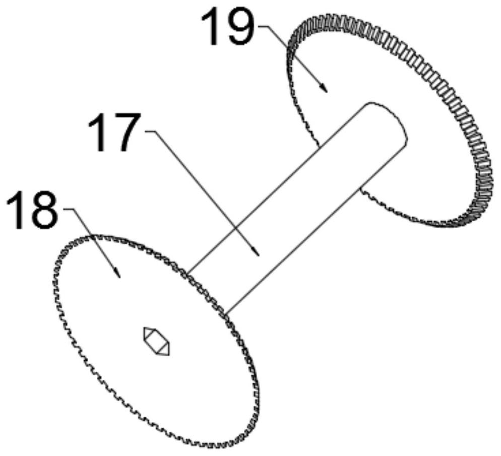
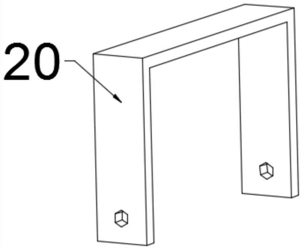
[0021] Example 1: Please refer to Figure 1-3 , a kind of electrical discharge machining equipment, comprising a lower base plate 1 and an upper base plate 2, a longitudinal drive device 3 is fixedly connected to the left side of the top of the upper base plate 2, an upper beam 4 is fixedly connected to the top of the longitudinal drive device 3, and an upper beam 4 is fixedly connected below the upper beam 4 The first chute 5, the horizontal driving device 6 is slidably connected to the lower part of the first chute 5, the electric discharge machining assembly 7 is fixedly connected to the lower part of the horizontal driving device 6, and the left and right symmetrical support frames 8 are fixedly connected to the bottom of the lower bottom plate 1. A motor 9 is fixedly connected to the lower middle part of the base plate 1, and the axis of the motor 9 runs through the lower base plate 1 and is connected with a driving bevel gear 10;
[0022] When in use, the position contro...
Embodiment 2
[0033] Embodiment two: refer to Figure 1-3 , a kind of electrical discharge machining equipment, comprising a lower base plate 1 and an upper base plate 2, a longitudinal drive device 3 is fixedly connected to the left side of the top of the upper base plate 2, an upper beam 4 is fixedly connected to the top of the longitudinal drive device 3, and an upper beam 4 is fixedly connected below the upper beam 4 The first chute 5, the horizontal driving device 6 is slidably connected to the lower part of the first chute 5, the electric discharge machining assembly 7 is fixedly connected to the lower part of the horizontal driving device 6, and the left and right symmetrical support frames 8 are fixedly connected to the bottom of the lower bottom plate 1. A motor 9 is fixedly connected to the lower middle part of the base plate 1, and the axis of the motor 9 runs through the lower base plate 1 and is connected with a driving bevel gear 10;
[0034] When in use, the position control ...
PUM
 Abstract
Description
Claims
Application Information
 - R&D Engineer
- R&D Manager
- IP Professional
- Industry Leading Data Capabilities
- Powerful AI technology
- Patent DNA Extraction
Browse by: Latest US Patents, China's latest patents, Technical Efficacy Thesaurus, Application Domain, Technology Topic, Popular Technical Reports.
© 2024 PatSnap. All rights reserved.Legal|Privacy policy|Modern Slavery Act Transparency Statement|Sitemap|About US| Contact US: help@patsnap.com