Chip and dust removal device of processing machine tool

A technology of dust removal device and processing machine tool, which is applied in metal processing machinery parts, metal processing equipment, manufacturing tools, etc., can solve the problems of cumbersome transfer processing, large dust removal load, affecting the production efficiency and quality of processing machine tools, etc., so as to improve by-products and recover value, reduce energy consumption and cost, ensure continuous operation and process quality effect

Inactive Publication Date: 2021-01-08
苏州艾米欧精密机械股份有限公司
View PDF12 Cites 5 Cited by
  • Summary
  • Abstract
  • Description
  • Claims
  • Application Information

AI Technical Summary

Problems solved by technology

[0002] Machine tool processing refers to the process of relying on the machine tool to ensure the relative motion relationship between the tool and the fixture, and at the same time use the tool to process the workpiece installed on the fixture, using the logic processing code of the automatic control program system to control the movement of the machine tool, including milling, boring, drilling , tapping and cutting threads, etc., which better solve the complex, precise, small batch and multi-variety parts processing problems, and waste chips will be generated in various processing processes, and the cooling water is also used to cool the tool and the workpiece. To ensure the quality of the section and tool life, the mixture of waste chips and cooling water needs to be discharged and collected in time to avoid affecting the machining of the machine tool. When recycling waste chips only by filtration, there is a large amount of static processing, which is difficult to recover immediately. The water content in waste chips is large. For There are mixed phenomena in the collection of waste chips of different qualities, which require subsequent cumbersome transfer treatment. At the same time, there is still a certain amount of dust in the process of processing, which makes it difficult to remove chips and dust and carry out continuous processing. The dust removal load is large, which affects the production efficiency of the processing machine tool. and quality

Method used


Image

  • Chip and dust removal device of processing machine tool
  • Chip and dust removal device of processing machine tool
  • Chip and dust removal device of processing machine tool

Examples


Embodiment Construction

[0020] The specific embodiments of the present invention will be further described below in conjunction with the accompanying drawings.

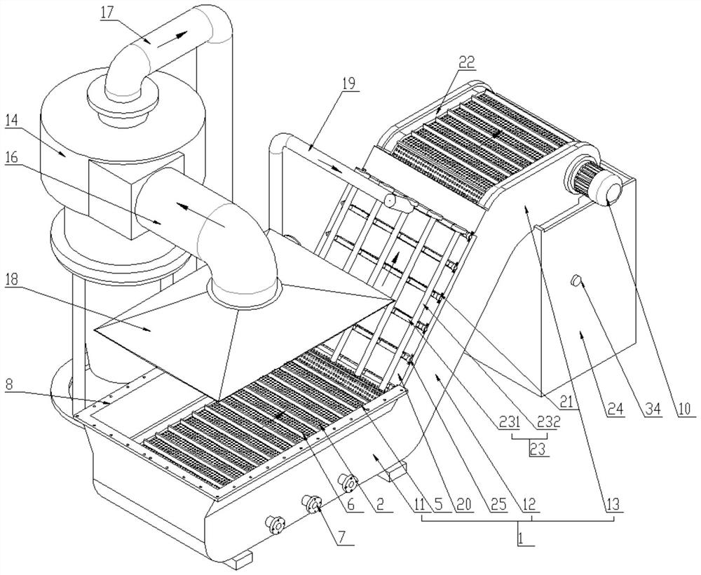
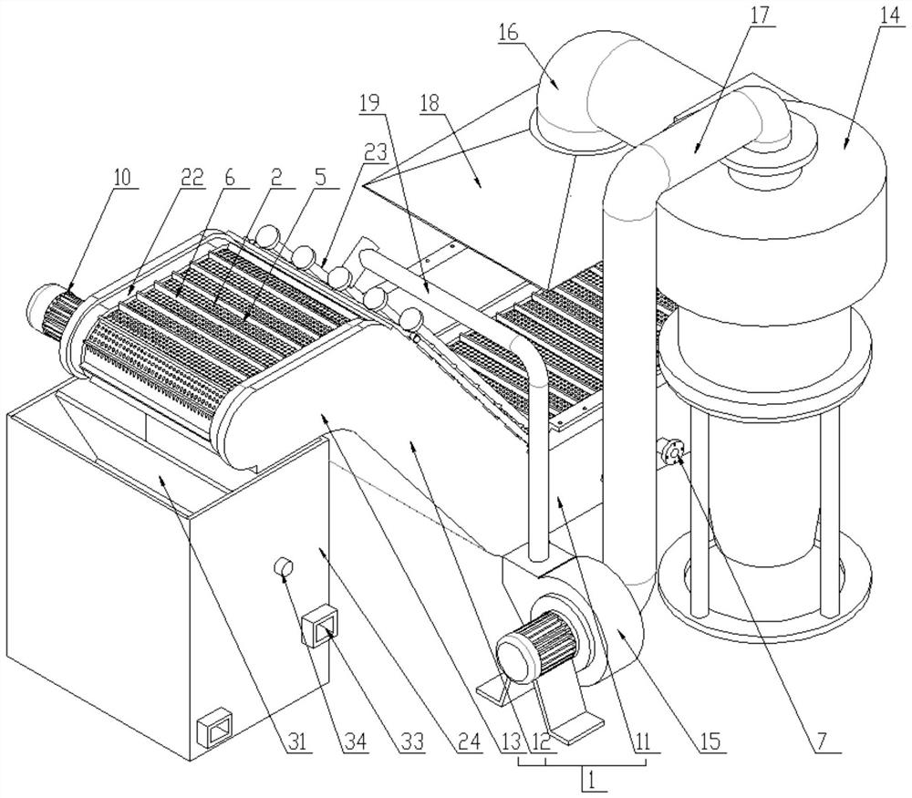
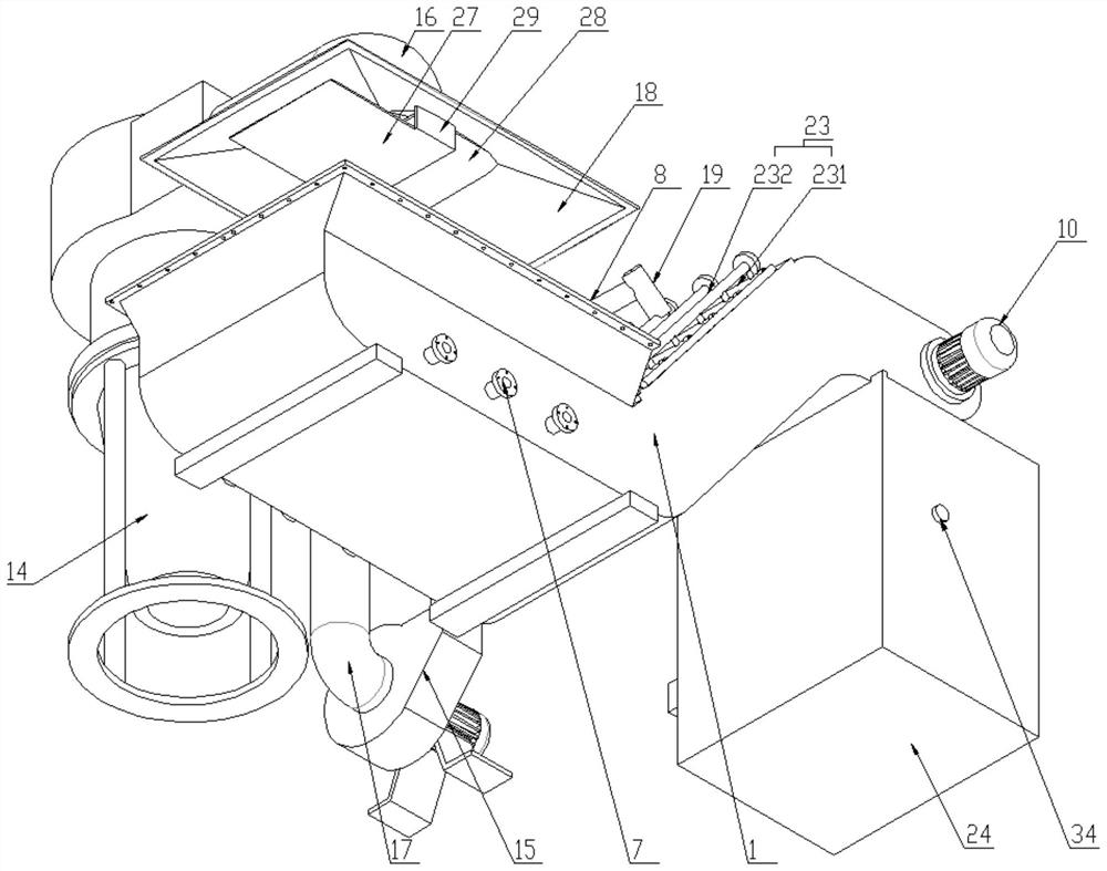
[0021] A chip removal and dust removal device for a processing machine tool, comprising a frame 1, wherein the frame 1 includes a water tank 11 with an open top, a lifting frame 12 and a transfer frame 13 connected in one structure, and the frame 1 is provided with a The conveyor belt 2 that rotates between the water tank 11, the lifting frame 12 and the transfer frame 13, the two ends of the conveyor belt 2 are provided with synchronously rotating driving rollers 3 and driven rollers 4, and the conveyor belt 2 is provided with a number of rollers distributed in an array. The permeable holes 5 and several belt plates 6 arranged at intervals, the side of the water tank 11 is provided with at least one water outlet 7;

[0022] The top of the water tank 11 is provided with an outwardly expanded opening flange 8, and the conveyor belt 2 is provi...


PUM


Abstract

The invention relates to a chip and dust removal device of a processing machine tool. The chip and dust removal device comprises a rack, wherein the rack comprises a water tank, a lifting frame and atransfer frame, a plurality of water permeable holes and a material carrying plate are arranged on a conveying belt, a blowing mechanism is arranged outside the lifting frame, a material collecting box is arranged at the bottom of the transfer frame, a cyclone dust collector and a fan are arranged on one side of the rack, an air suction hopper is connected to the end of an air inlet pipe of the cyclone dust collector, an air conveying pipe is arranged between the fan and the purging mechanism, a C-shaped magnet is arranged in a driving roller, and a material baffle and a material partition which are obliquely arranged are arranged in the material collecting box. According to the chip and dust removal device, a large number of waste mixtures containing water of the processing machine tool can be continuously treated in time, the preliminary separation of chips from water is combined with blowing separation, cyclone separation is combined with blowing adsorption, so that dust is efficiently treated, the dust removal load is reduced, cooling water is recycled, energy consumption and cost are reduced, and waste materials are separated and collected, so that byproducts and recycling values are increased, and continuous operation and machining quality of the processing machine tool are guaranteed.

Description

technical field [0001] The invention relates to a chip removal and dust removal device for a processing machine tool, which belongs to the technical field of processing machine tools. Background technique [0002] Machine tool processing refers to the process of relying on the machine tool to ensure the relative motion relationship between the tool and the fixture, and at the same time use the tool to process the workpiece installed on the fixture, using the logic processing code of the automatic control program system to control the movement of the machine tool, including milling, boring, drilling , tapping and cutting threads, etc., which better solve the complex, precise, small batch and multi-variety parts processing problems, and waste chips will be generated in various processing processes, and the cooling water is also used to cool the tool and the workpiece. To ensure the quality of the section and tool life, the mixture of waste chips and cooling water needs to be d...

Claims


Application Information

Patent Timeline
Patent Type & Authority Applications(China)
IPC IPC(8): B23Q11/00
CPCB23Q11/0042B23Q11/0064B23Q11/0046
Inventor 赵海军
Owner 苏州艾米欧精密机械股份有限公司
Why Eureka
Try Eureka