Grouting anchor rod cable combined beam for advanced supporting of deep broken surrounding rock and support method

A technology of grouting bolts and composite beams, which is applied in the directions of supporting the roof beams of the mine roof, installing bolts, and earth-moving drilling, etc. Guiding on-site grouting construction, inability to install pallets, etc., to improve the stress state of surrounding rock, improve integrity and self-supporting force, and avoid blindness

Active Publication Date: 2021-01-08
SHANDONG UNIV OF SCI & TECH
View PDF9 Cites 3 Cited by
  • Summary
  • Abstract
  • Description
  • Claims
  • Application Information

AI Technical Summary

Problems solved by technology

However, this method is only limited to indoor tests under ideal conditions, and cannot effectively guide on-site grouting construction; in addition, this method only considers the diffusion law of grouting fluid in the internal cracks of rocks, and cannot simulate the anchor rod or anchor cable. Reinforcement and support for rock
[0008] In addition, the grouting anchor trays used in the above technologies are all traditional trays. Although the trays of this structure are theoretically suitable for drilling with any inclination, it is found in practical applications that when the drilling inclination is large and multiple drills When the slopes of the holes are inconsistent, there will be situations where the fastening nuts and pallets of some anchor rods cannot be installed. In addition, multiple anchor rods are drilled in a certain area at the same time, and the inclination angles of the multiple anchor rods are different, which causes the pallet installation to be difficult. Difficulties and overlapping situations

Method used


Image

  • Grouting anchor rod cable combined beam for advanced supporting of deep broken surrounding rock and support method
  • Grouting anchor rod cable combined beam for advanced supporting of deep broken surrounding rock and support method
  • Grouting anchor rod cable combined beam for advanced supporting of deep broken surrounding rock and support method

Examples


Embodiment Construction

[0074] The preferred embodiments of the present invention will be described in detail below in conjunction with the accompanying drawings, so that the advantages and features of the present invention can be more easily understood by those skilled in the art, so as to define the protection scope of the present invention more clearly.

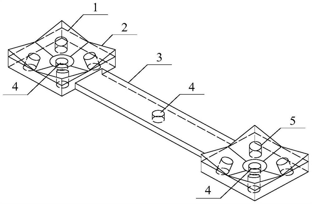
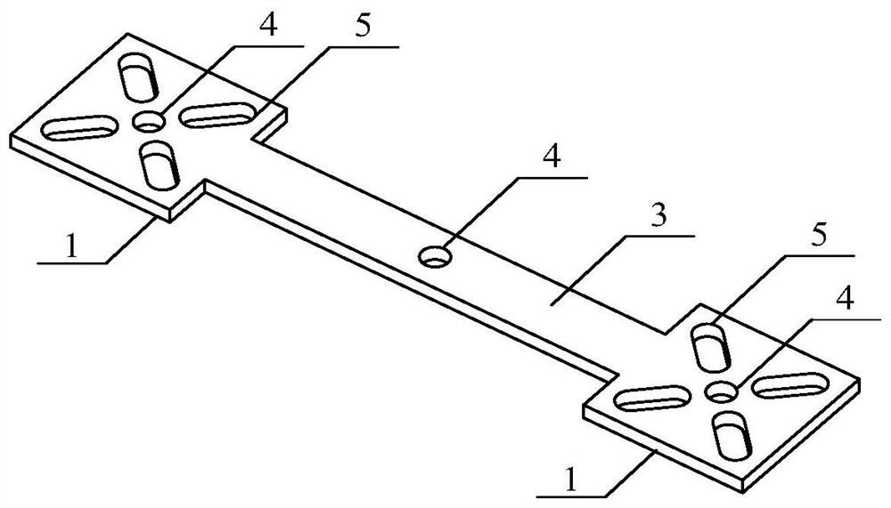
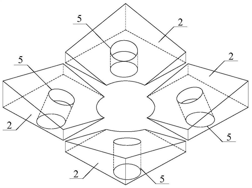
[0075] The pallet used in the composite beam of the present invention refers to image 3 As shown, what is shown in the figure is the state that four pallets are arranged on the guard plate 1, as can be seen from the figure, the pallet is a wedge-shaped spacer 2, and the upper and lower sides of the wedge-shaped spacer 2 are planes and slopes respectively. The wedge-shaped spacer 2 is provided with an anchor rod hole 5, and the angle of the slope of the wedge-shaped spacer 1 should ensure that when the pallet is in use, the anchor rod is arranged vertically to the pallet slope, that is to say, the anchor rod hole 5 is perpendicular to the pallet s...


PUM


Abstract

The invention discloses a grouting anchor rod cable combined beam for advanced supporting of deep broken surrounding rock and a supporting method. Square protective plates are fixed to the two ends ofa steel beam respectively, anchor cable holes are formed in the center of the steel beam and the centers of the protective plates, and the hole diameter is larger than the diameter of anchor cables;four anchor rod holes are formed in the protective plates, each anchor rod hole corresponds to one wedge-shaped cushion block, the plane of each wedge-shaped cushion block is tightly attached to the protective plates, the arc-shaped portions of four trays face the centers of the protective plates, grouting anchor rods sequentially penetrate through the trays and the protective plates and are fixedin a roof rock stratum through anchoring agents, and the free ends of the anchor rods apply pre-tightening force through nuts; and the anchor cables penetrate through the anchor cable holes and are fixed in an overlying stable rock stratum through the anchoring agents, and the free ends of the anchor cables are fixed through a rigging. According to the grouting anchor rod cable combined beam foradvanced supporting of deep broken surrounding rock and the supporting method, the shallow part and the deep part of a mining roadway are sequentially grouted and constructed by utilizing the combinedbeam, so that graded progressive reinforcement of the surrounding rock of the mining roadway from shallow to deep and from outside to inside is realized, and the control and maintenance of the miningroadway under the conditions of weak and broken roofs are facilitated.

Description

technical field [0001] The invention relates to the technical field of mining engineering support, in particular to a grouting-bolt-cable composite beam and a support method for advanced support of high-stress broken surrounding rock in deep mining roadways. Background technique [0002] At present, coal resources account for about 60% of my country's primary energy consumption, and underground mining accounts for about 90% of coal resource production. In the underground mining process, a large number of roadways need to be excavated every year, and the support is generally divided into two stages, namely, the permanent support in the roadway excavation stage and the advanced support in the recovery preparation stage. The advanced support of the working face has always been the focus and difficulty restricting the safe and efficient production of coal mines. Especially for the deep broken surrounding rock conditions, due to the double influence of high ground stress and mult...

Claims


Application Information

Patent Timeline
Patent Type & Authority Applications(China)
IPC IPC(8): E21D20/02E21D21/00E21D11/15E21D11/10E21B47/002E21B49/00
CPCE21D20/02E21D21/0086E21D11/155E21D11/10E21B49/00E21D17/00E21D21/008E21D21/0093
Inventor 刘学生范德源谭云亮杨康宋世琳武允昊李学斌王新
Owner SHANDONG UNIV OF SCI & TECH
Why Eureka
Try Eureka