Transient compensation control system and method for gas generator

A gas generator, compensation control technology, applied in the direction of engine control, electrical control, combustion engine, etc., can solve the problems that the gas generator cannot meet, the dynamic response of the gas generator is not good, lag, etc.

Pending Publication Date: 2021-01-08
广西玉柴船电动力有限公司
View PDF0 Cites 0 Cited by
  • Summary
  • Abstract
  • Description
  • Claims
  • Application Information

AI Technical Summary

Problems solved by technology

[0004] The mixed gas intake mode of gas engines for industrial power generation is mostly premixed. Air and gas form a combustible mixed gas in the mixer. The mixed gas flows through multiple intake pipes in sequence before finally reaching the combustion chamber. The existing technology The gas compensation position used in the system is generally set at the end of the mixer, far away from the combustion chamber of the gas generator. When the gas compensation amount is required, too many pipelines pass through, so it takes a certain amount of time for the transient compensation amount to reach the combustion of each cylinder. At this time, the change of combustion speed has lagged behind the change of speed, which will cause the gas generator to fail to meet the requirements of certain standards or working conditions under some sudden load or unloading conditions, so gas-fired power generation The machine is not good in terms of dynamic response

Method used


Image

  • Transient compensation control system and method for gas generator
  • Transient compensation control system and method for gas generator
  • Transient compensation control system and method for gas generator

Examples


Embodiment Construction

[0054] The embodiment of the present application provides a gas generator transient compensation control system and method, which can effectively improve the dynamic response of the gas generator and meet the requirements of certain standards or working conditions.

[0055] The technical solution in this application will be clearly and completely described below in conjunction with the accompanying drawings in the embodiments of this application. Obviously, the described embodiments are only some of the embodiments of this application, not all of them. Based on the embodiments in this application, all other embodiments obtained by persons of ordinary skill in the art without making creative efforts belong to the scope of protection of this application.

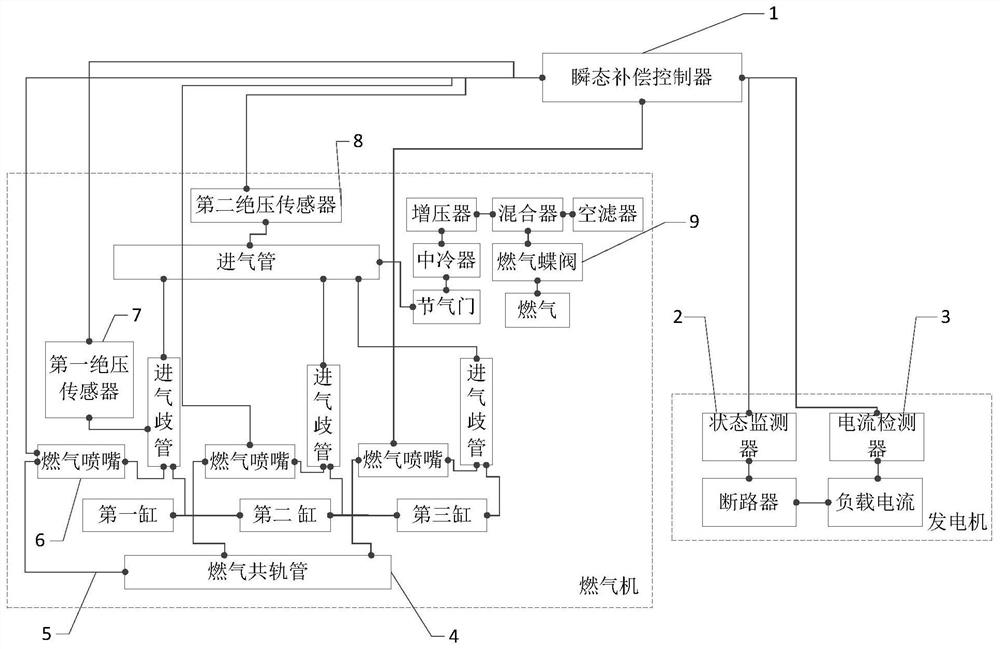
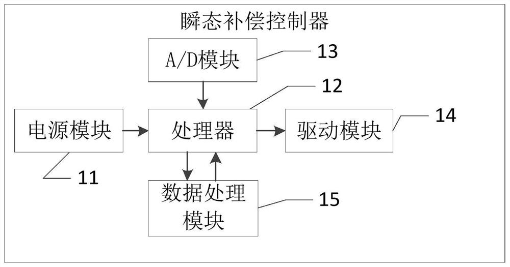
[0056]see Figure 1 to Figure 2 , the embodiment of the present application discloses a gas generator transient compensation control system, including: a transient compensation controller 1, a state monitor 2, a circuit breake...


PUM


Abstract

The embodiment of the invention discloses a transient compensation control system and method for a gas generator. The transient compensation control system and method for the gas generator can effectively improve the dynamic responsiveness of the gas generator and meet the requirements of certain standards or working conditions. According to the system, a transient compensation controller is electrically connected with a state monitor; the state monitor is electrically connected with a circuit breaker; the transient compensation controller is electrically connected with a current detector; thetransient compensation controller is electrically connected with a first absolute pressure sensor, a second absolute pressure sensor, a gas nozzle and a gas butterfly valve; the current detector is used for detecting the current change rate, and the transient compensation controller controls the gas nozzle to be opened and closed according to a signal of the current change rate in cooperation with a load pressure signal fed back by the second absolute pressure sensor and a pressure drop signal fed back by the first absolute pressure sensor; and the state monitor is used for sending a signal that the circuit breaker is in a disconnected state to the transient compensation controller, and the transient compensation controller reduces the opening degree of the gas butterfly valve according to the signal that the circuit breaker is in the disconnected state.

Description

technical field [0001] The embodiment of the present application relates to the gas generator industry, in particular to a gas generator transient compensation control system and method. Background technique [0002] Gas generator is a new type of high-efficiency new energy generator that uses combustible gases such as liquefied petroleum gas and natural gas as the fuel to replace gasoline and diesel as engine power. The gas generator maintains a certain speed under normal conditions, but when running In the case of sudden loading in the working condition, the speed of the gas generator will change. The response time of the gas generator under the condition of sudden loading at a constant speed is long, the ability to resist load impact is poor, the fluctuation rate of the speed is large, and the speed recovery time is too long. As a result, it is difficult for gas generator sets to meet the requirements of certain standards or working conditions. [0003] In the face of th...

Claims


Application Information

Patent Timeline
IPC IPC(8): F02D41/00F02D41/30F02M21/02F02B63/04
CPCF02D41/0027F02D41/30F02M21/023F02M21/0239F02M21/0215F02B63/04Y02T10/30
Inventor 张彬曾志龙莫员
Owner 广西玉柴船电动力有限公司
Why Eureka
Try Eureka