User-centric unmanned aerial vehicle base station multi-beam joint transmission method

A joint transmission and unmanned aerial vehicle technology, applied in the field of wireless communication, can solve problems such as reducing user signal-to-noise ratio, increasing unmanned aerial vehicle co-frequency interference, and data fluctuations

Inactive Publication Date: 2021-01-12
BEIJING UNIV OF POSTS & TELECOMM
View PDF4 Cites 4 Cited by
  • Summary
  • Abstract
  • Description
  • Claims
  • Application Information

AI Technical Summary

Problems solved by technology

However, the hardware configuration of a single UAV is limited, and it cannot provide users with durable and stable services; the greater probability of line-of-sight of UAVs improves t...

Method used


Image

  • User-centric unmanned aerial vehicle base station multi-beam joint transmission method
  • User-centric unmanned aerial vehicle base station multi-beam joint transmission method
  • User-centric unmanned aerial vehicle base station multi-beam joint transmission method

Examples


Embodiment Construction

[0024] The implementation method of the present invention will be described in detail below in conjunction with the accompanying drawings.

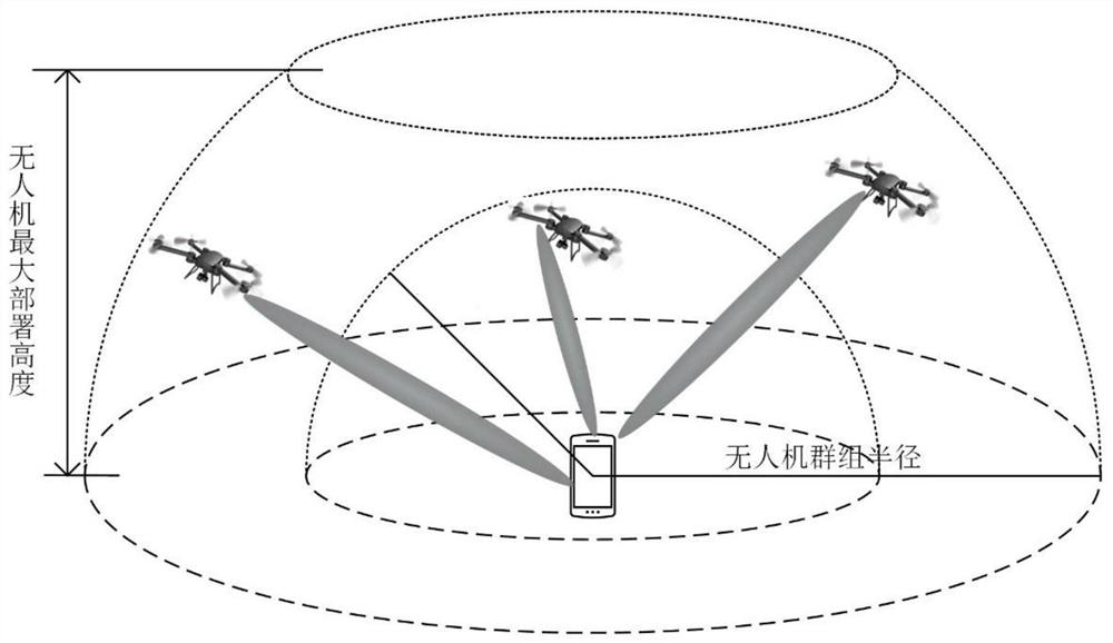
[0025] figure 1 It is a schematic diagram of the user-centered UAV base station multi-beam joint transmission method of the present invention. The network dynamically builds a user-centric UAV group for users, and collaborates on transmission within the group. As the user moves, the user's service drone group is constantly updated dynamically.

[0026] Each UAV station is equipped with F antennas, and provides services for F users respectively according to the downlink channel state information CSI. The user determines the UAV group Φ based on the selected UAV group signal condition threshold η and the reference signal received power RSRP received by the user v . Consider the UAV LOS / NLOS link characteristics, the probability of line-of-sight and non-line-of-sight can be modeled as a function of UAV elevation angle,

[0027]

[...


PUM


Abstract

An unmanned aerial vehicle base station becomes an important candidate solution for future B5G/6G network coverage and capacity enhancement by means of high mobility, higher line-of-sight probabilityand flexible deployment characteristics. However, the communication capability of a single unmanned aerial vehicle is limited, and durable and stable services cannot be provided for users. Meanwhile,the large-probability line-of-sight link of the unmanned aerial vehicle also brings strong same-frequency interference while improving the quality of a service link. Therefore, in order to ensure theconsistency and continuity of unmanned aerial vehicle network services, the invention provides an unmanned aerial vehicle base station group taking a user as a center, and unmanned aerial vehicles inthe group serve the user at the same time in a joint transmission (JT) mode so as to enhance the robustness of data transmission. Particularly, each unmanned aerial vehicle is provided with F antennasto provide services for multiple users at the same time, and zero-forcing beamforming is adopted to reduce inter-cell interference. Simulation results show that the network signal-to-interference ratio coverage rate, the unmanned aerial vehicle group size and the unmanned aerial vehicle deployment height are optimal.

Description

technical field [0001] The present invention relates to the technical field of wireless communication, and in particular to research on a user-centered multi-beam joint transmission method for UAV base stations under the fifth generation mobile communication (Beyond 5thGeneration, B5G) and sixth generation mobile communication (6th Generation, 6G) in the future. Background technique [0002] In the future, while the B5G / 6G network provides more resources to meet the growing demand for high speed, it will also expand the scope of application more widely to achieve ubiquitous "ubiquitous connection". The deployment of ground base stations often has a long cycle and high cost, which makes the existing ground base station deployment schemes not suitable for high dynamic business scenarios: large-capacity heating scenarios (distribution of hotspot areas, panoramic video live broadcast, etc.) and high-coverage blindness compensation scenarios (disaster relief emergency, public sec...

Claims


Application Information

Patent Timeline
IPC IPC(8): H04B7/0413H04B7/0456H04J11/00H04L5/00H04W16/18
CPCH04B7/0413H04B7/0456H04J11/005H04L5/0048H04W16/18
Inventor 张鸿涛唐文斐何元周明宇
Owner BEIJING UNIV OF POSTS & TELECOMM
Why Eureka
Try Eureka