
Method for producing a fibre-reinforced pressure vessel with pole cap reinforcement

A technology of pressure tanks and reinforcements, which is applied in the manufacture of pressure vessels, vessel structures, and outer walls of vessel structures, and can solve problems such as increasing production workload

Active Publication Date: 2021-01-12
奈普奥私营有限公司
View PDF14 Cites 3 Cited by
  • Summary
  • Abstract
  • Description
  • Claims
  • Application Information

AI Technical Summary

Problems solved by technology

This specific winding device also increases the necessary production effort

Method used


Image

  • Method for producing a fibre-reinforced pressure vessel with pole cap reinforcement
  • Method for producing a fibre-reinforced pressure vessel with pole cap reinforcement
  • Method for producing a fibre-reinforced pressure vessel with pole cap reinforcement

Examples


Embodiment Construction

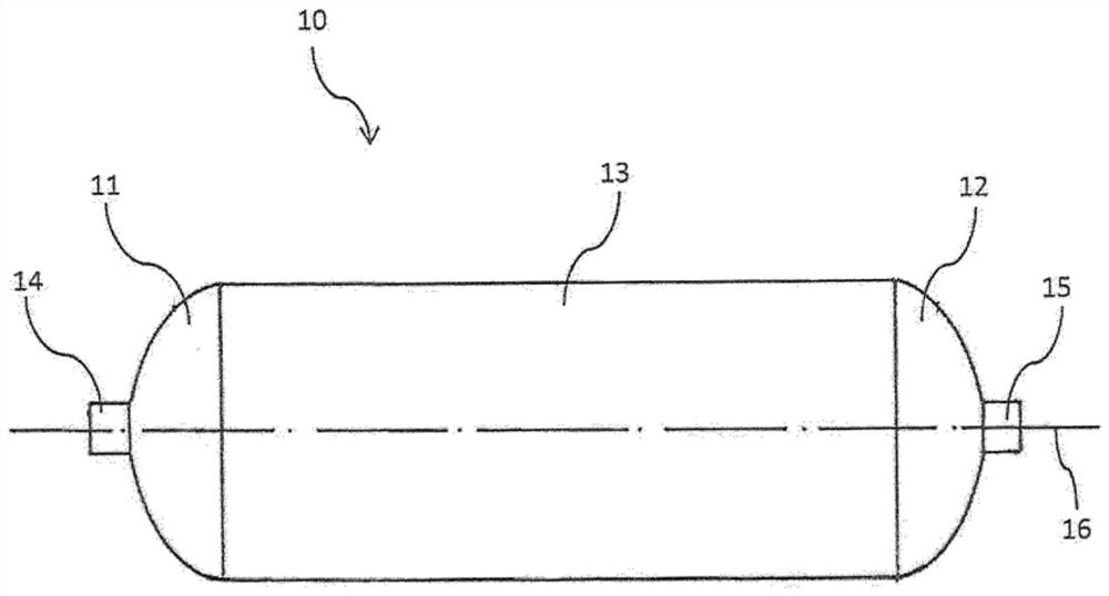
[0046] figure 1 A pressure tank or a composite pressure tank, respectively, produced by the method according to the invention is shown in . The pressure vessel 10 has a cylindrical central part 13 and two protruding pole caps 11 and 12 for closing the opening of the cylindrical central part 13 . Protruding connecting flanges 14 and 15 may be provided on these pole caps 11 , 12 , the shape and arrangement of these flanges 14 , 15 being shown by way of example only. The cylindrical central part 13 has ends adjoining the protruding pole caps 11 , 12 .

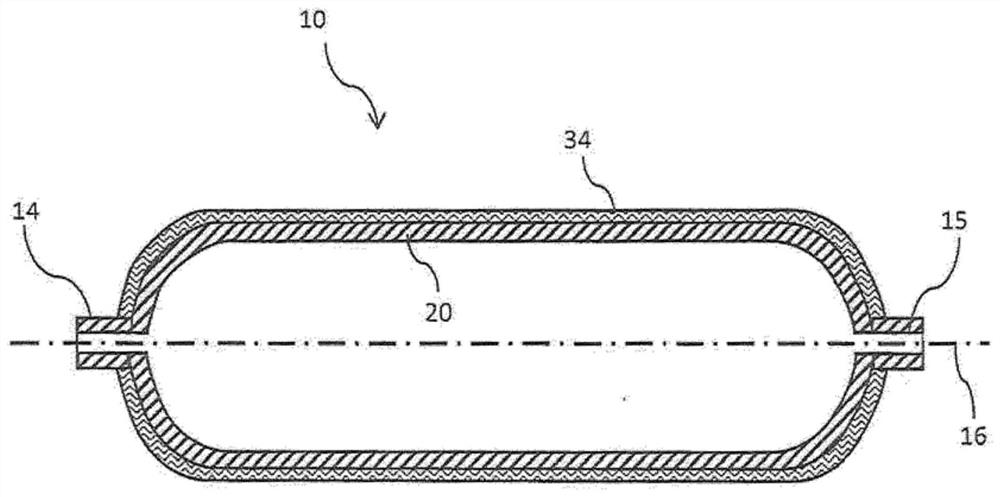
[0047] Such a pressure tank 10 is produced by reinforcing the inner vessel with an outer layer made of fiber reinforcement. figure 2 This structure of the pressure tank 10 is shown in a schematic longitudinal section. An outer layer 34 made of reinforcing fibers is wrapped around the inner container 20 . The shape of the inner container 20 substantially corresponds to the shape of the pressure tank 10 to be produced, so that ...


PUM


Abstract

The invention relates to a method for producing a pressure vessel (10), comprising an inner vessel (20) and an outer layer (34) wound onto the inner vessel (20) and consisting of a fibre material. Inthe method, a holding device having multiple holding elements protruding therefrom is attached to an inner vessel (20) in order to wind a local pole cap reinforcement in a dome-shaped pole cap region(21;22) of the inner vessel. The holding device is then removed and an outer layer (340 is produced by winding fibre material, the outer layer (34) enclosing the central region (23) and the pole cap regions (21;22) of the inner vessel (20).

Description

technical field [0001] The invention relates to a method of manufacturing a pressure tank comprising an inner container and an outer layer of fibrous material wrapped around the inner container. Background technique [0002] As part of the global effort to reduce CO2 emissions, an increasing number of alternative drive units for vehicles are being developed and placed on the market. One trend is electrification, as an alternative to battery-powered vehicles, also offering fuel cells. In the field of vehicle development, efforts are being made to convert various types of vehicles to electric drive, where energy is mainly provided by fuel cells. The hydrogen required for this purpose is stored in high-pressure tanks. In order to minimize the weight for these mobile applications, Type 4 pressure tanks are preferably used, especially with fibre-reinforced plastic liners, preferably with CFK reinforcements. [0003] These vessels consist of a cylindrical central part flanked o...

Claims


Application Information

Patent Timeline
Patent Type & Authority Applications(China)
IPC IPC(8): F17C1/16F17C1/06
CPCF17C1/06F17C1/16F17C2201/0104F17C2201/0109F17C2201/056F17C2201/058F17C2203/0604F17C2203/0607F17C2203/0619F17C2203/0656F17C2203/0663F17C2209/2154F17C2221/012F17C2223/0123F17C2270/0168F17C2270/0178Y02E60/32B29C53/56B29C53/80B29D22/003F17C2209/232
Inventor 崔斯坦·鲍默
Owner 奈普奥私营有限公司
Learn More