Automatic control method for boiler flue gas baffle of ultra-supercritical generator set

A technology for boiler flue gas and generator sets, which is applied in separation methods, chemical instruments and methods, and dispersed particle separation, etc., can solve the problems of catalyst wear, excessive denitration emissions, catalyst side reactions, etc. Hot steam temperature, the effect of improving work efficiency

Active Publication Date: 2021-01-15
HUANENG POWER INT INC
View PDF11 Cites 0 Cited by
  • Summary
  • Abstract
  • Description
  • Claims
  • Application Information

AI Technical Summary

Problems solved by technology

[0003] When the load is reduced to below 50% of the rated load, the inlet flue temperature of the denitrification reactor can only be increased by manually fully opening the flue gas baffle on the lower side of the boiler and fully closing the flue gas baffle on the lower side of the boiler. In this way, it is easy to make the flue gas temperature lower than the lower limit of the applicable temperature range of the denitrification catalyst, which will cause a side reaction on the catalyst: NH 3 with SO 3 and H 2 O reaction produces (NH 4 ) 2 SO 4 or NH 4 HSO 4 , to reduce the reaction with NOX, the product adheres to the surface of the catalyst, blocks the channels and micropores of the catalyst, and reduces the activity of the catalyst; at the same time, local blockage will also cause wear of the catalyst
It may also cause the differential pressure of the air preheater and the differential pressure of the smoke cooler to increase, seriously affecting the safe operation of the unit and even causing the denitration emission to exceed the standard
[0004] However, this operation mode makes the average temperature of boiler reheat steam only about 560°C, which is much lower than the designed rated operating temperature of 603°C, which seriously affects the safe and economical operation of the unit.

Method used


Image

  • Automatic control method for boiler flue gas baffle of ultra-supercritical generator set
  • Automatic control method for boiler flue gas baffle of ultra-supercritical generator set
  • Automatic control method for boiler flue gas baffle of ultra-supercritical generator set

Examples


Embodiment

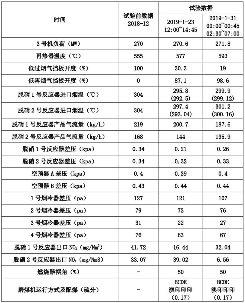
[0027] Huaneng Shanghai Shidongkou No. According to the various parameters of the boiler during low-load operation under the means, it can be seen that the average reheat steam temperature is only 555°C under the condition of satisfying the normal operation of denitrification.

[0028] time 2018-12 Unit 3 load (MW) 270 Reheat steam temperature (℃) 555 Lower smoke baffle opening (%) 100 Low re-smoke gas baffle opening (%) 0 Inlet flue temperature of denitrification No. 1 reactor (°C) 304 Inlet flue temperature of No. 2 denitrification reactor (°C) 304 Product gas flow rate of No. 1 denitrification reactor (kg / h) 219 Product gas flow rate of No. 2 denitrification reactor (kg / h) 168 Differential pressure of No. 1 denitrification reactor (kpa) 0.34 Differential pressure of No. 2 denitrification reactor (kpa) 0.34 Air preheater A differential pressure (kpa) 0.4 Air preheater B differential pressure (kpa...


PUM


Abstract

The invention relates to an automatic control method for a boiler flue gas baffle of an ultra-supercritical generator set, which comprises the following steps of: 1, constructing a basic automatic control logic of a flue gas baffle, and determining an applicable temperature range of a denitration catalyst; 2, based on the basic automatic control logic of the flue gas baffle in the step 1, furtheradding a control logic for the flue gas temperature of the denitration inlet to ensure that the flue gas baffle only adjusts the temperature of the reheated steam; 3, based on the basic automatic control logic of the flue gas baffle in the step 1, further adding a limiting condition logic used for ensuring that manual intervention of the flue gas baffle is not needed during low load; and 4, forming an integral control logic for the boiler flue gas baffle based on the steps 1, 2 and 3, and performing actual automatic control on the boiler flue gas baffle by utilizing the integral control logic.Compared with the prior art, the method has the advantages that the temperature of the reheated steam is increased, and safe, economical and environment-friendly operation of the unit is ensured.

Description

technical field [0001] The invention relates to the technical field of ultra-supercritical generating sets, in particular to an automatic control method for boiler flue gas baffles used in ultra-supercritical generating sets. Background technique [0002] At present, the automatic control logic of the boiler flue gas baffle of the 660MW ultra-supercritical generating set only participates in the adjustment of the reheating steam temperature of the boiler. [0003] When the load is reduced to below 50% of the rated load, the inlet flue temperature of the denitrification reactor can only be increased by manually fully opening the flue gas baffle on the lower side of the boiler and fully closing the flue gas baffle on the lower side of the boiler. In this way, it is easy to make the flue gas temperature lower than the lower limit of the applicable temperature range of the denitrification catalyst, which will cause a side reaction on the catalyst: NH 3 with SO 3 and H 2 O rea...

Claims


Application Information

Patent Timeline
Patent Type & Authority Applications(China)
IPC IPC(8): B01D53/86B01D53/34B01D53/56
CPCB01D53/346B01D53/8625
Inventor 王学海陈佳伟郭强倪佳钱晓迪陈凌霄袁晓磊
Owner HUANENG POWER INT INC
Why Eureka
Try Eureka