Eureka AIR delivers breakthrough ideas for toughest innovation challenges, trusted by R&D personnel around the world.

Metal-air fuel battery stack with easily-replaced open anode

A fuel cell stack and metal-air technology, applied to battery pack parts, fuel cell half-cells, secondary battery half-cells, secondary batteries, etc., can solve the problems of metal waste and cumbersome procedures, and achieve Simplified maintenance, thorough cooling, and improved inspection efficiency

Active Publication Date: 2021-01-15
TRANSLATIONAL RES CENT SCHOOL OF MECHANICAL & VEHICLE BEIJING INST OF TECH TANGSHAN PORT ECONOMIC DEV ZONE
View PDF6 Cites 0 Cited by
  • Summary
  • Abstract
  • Description
  • Claims
  • Application Information

AI Technical Summary

Problems solved by technology

During the replacement process of traditional metal-air fuel cells, it is necessary to check whether the metal electrodes are completely reacted one by one, and it is necessary to interrupt the power supply and disassemble the metal electrodes, and the procedures are cumbersome. , causing waste of metal

Method used


Image

  • Metal-air fuel battery stack with easily-replaced open anode
  • Metal-air fuel battery stack with easily-replaced open anode
  • Metal-air fuel battery stack with easily-replaced open anode

Examples


Embodiment 1

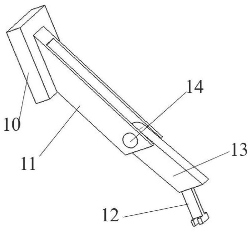
[0039] The metal-air fuel cell stack with an open anode easily replaceable in this embodiment includes: an electrolyte pool, an anode circulation device, a lifting bump, an anode connecting rod, an air electrode and a metal electrode.

[0040] figure 1 It is a schematic structural diagram of the electrolyte cell in Example 1 of the present invention. Such as figure 1 As shown, the electrolyte pool 1 in this embodiment is an annular electrolyte pool, the electrolyte pool 1 is filled with electrolyte, and all metal electrodes are vertically immersed in the electrolyte. An electrode tank 3 is provided on the side wall of the electrolyte pool 1, the air electrode is fixed in the electrode tank 3, the ion side of the air electrode is immersed in the electrolyte, and the air side of the air electrode is exposed to the electrolyte pool. 1 outside air. The electrode slot 3 is square in the figure. A large-area integrated air electrode can be installed in the electrode slot 3, whic...

Embodiment 2

[0050] In this embodiment, on the basis of Embodiment 1, a circulation system is added. Figure 5 It is a structural schematic diagram of Embodiment 2 of the present invention. Such as Figure 5 As shown, the circulation system in this embodiment includes a temperature sensor 22 , an electronic control unit 24 , a sedimentation tank 18 , a filter screen 17 , a circulation pump 16 and a radiator 15 . The outlet 2 of the electrolyte pool is connected to the first inlet of the sedimentation tank 18 by a pipeline, and the filter screen 17 is fixed at the outlet position in the sedimentation tank 18; the outlet of the sedimentation tank 18 passes through The pipeline is connected to the inlet of the circulation pump 16, the outlet of the circulation pump 16 is connected to the inlet of the radiator 15 through the pipeline, and the outlet of the radiator 15 is connected to the electrolyte pool through the pipeline. Liquid inlet 4. The temperature sensor 22 is fixed in the electro...


PUM


Abstract

The invention relates to a metal-air fuel battery stack with an easily-replaced open anode. All metal electrodes in the battery pack are positioned in an electrolyte tank; an air electrode is fixed inan electrode groove in the side wall of the electrolyte tank; a base of an anode circulating device is fixed on the electrolyte tank along the upper surface of the side wall of the electrolytic tank;a connecting rod conveying mechanism is fixed above the base through a bracket; a synchronous belt in the connecting rod conveying mechanism circularly operates in the connecting rod conveying mechanism; a lifting lug is fixed on the base; an upper-end connecting rod in the anode connecting rod is fixed on the synchronous belt, the upper-end connecting rod is movably connected with a lower-end connecting rod, and the lower-end connecting rod is fixedly connected with a fixing frame for clamping a metal electrode; and when the anode connecting rod rotates to the lifting lug, the lower-end connecting rod is positioned on the lifting lug, and the fixed frame brings the clamped metal electrode to the upper part of the electrolyte tank. The replacement efficiency of the metal electrode can beimproved.

Description

technical field [0001] The invention relates to the field of metal-air batteries, in particular to an open-type metal-air fuel cell stack with easily replaceable anodes. Background technique [0002] As a power battery widely used at present, the lithium-ion battery pack has the characteristics of high power density and long cycle life, and is widely used in power equipment. However, lithium-ion batteries also have their inherent defects. First, the energy density is low. In the field of electric vehicles that widely use lithium-ion batteries as energy sources, the low energy density of lithium-ion batteries has caused the cruising range of pure electric vehicles to be unsatisfactory; Lithium-ion batteries have higher requirements on the charging and discharging temperature. The general requirements are below 0°C, they cannot be charged, and below -10°C, they cannot work, which causes great inconvenience to the use in cold regions in winter. At the same time, the inherent s...

Claims


Application Information

Patent Timeline
Patent Type & Authority Applications(China)
IPC IPC(8): H01M12/08H01M10/42H01M50/77H01M50/609
CPCH01M10/4235H01M12/08Y02E60/10
Inventor 董明明张钰周阳梁靓
Owner TRANSLATIONAL RES CENT SCHOOL OF MECHANICAL & VEHICLE BEIJING INST OF TECH TANGSHAN PORT ECONOMIC DEV ZONE
Why Eureka
Eureka Blog
Learn More