
Composite sealing ball valve

A composite ball valve technology, applied in the shaft seal, valve details, valve device, etc., can solve the problems of long time consumption, gas waste, high maintenance cost, etc., and achieve the effect of convenient and quick replacement, low production cost and significant economic benefits

Pending Publication Date: 2021-01-19
呼和浩特中燃城市燃气发展有限公司
View PDF0 Cites 0 Cited by
  • Summary
  • Abstract
  • Description
  • Claims
  • Application Information

AI Technical Summary

Problems solved by technology

In the process of fastening the polytetrafluoroethylene packing layer, because it is at the critical temperature, it is easy to exceed the maximum compression ratio of 5% due to excessive pressure, so that the internal polytetrafluoroethylene packing has scales and completely destroys its seal. performance, unsatisfactory
To replace the valve, it is necessary to stop the gas transmission, and then replace and remove all the gas in the gas pipe network before it can be implemented. However, the amount of gas removed in the pipe network is huge, which takes a long time, causes a lot of waste of gas, and high maintenance costs

Method used

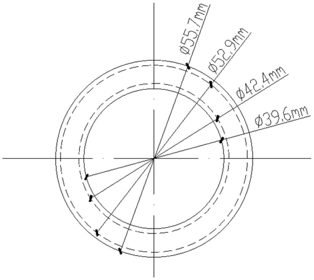
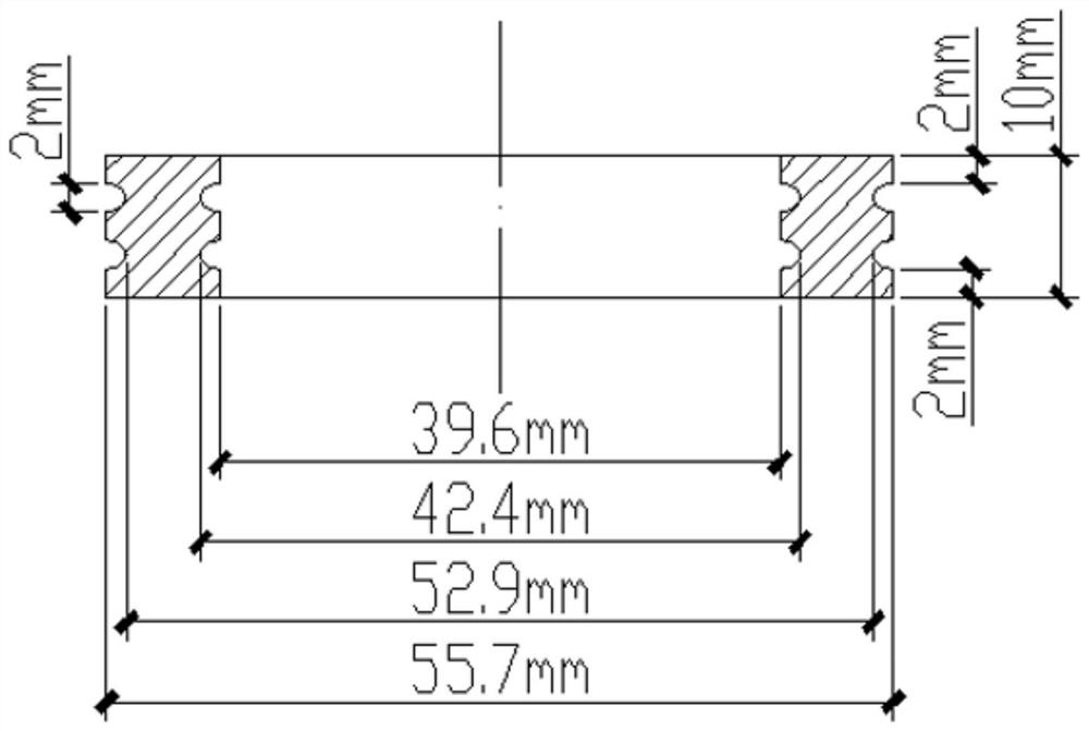

Image

  • Composite sealing ball valve
  • Composite sealing ball valve
  • Composite sealing ball valve

Examples


Embodiment 1

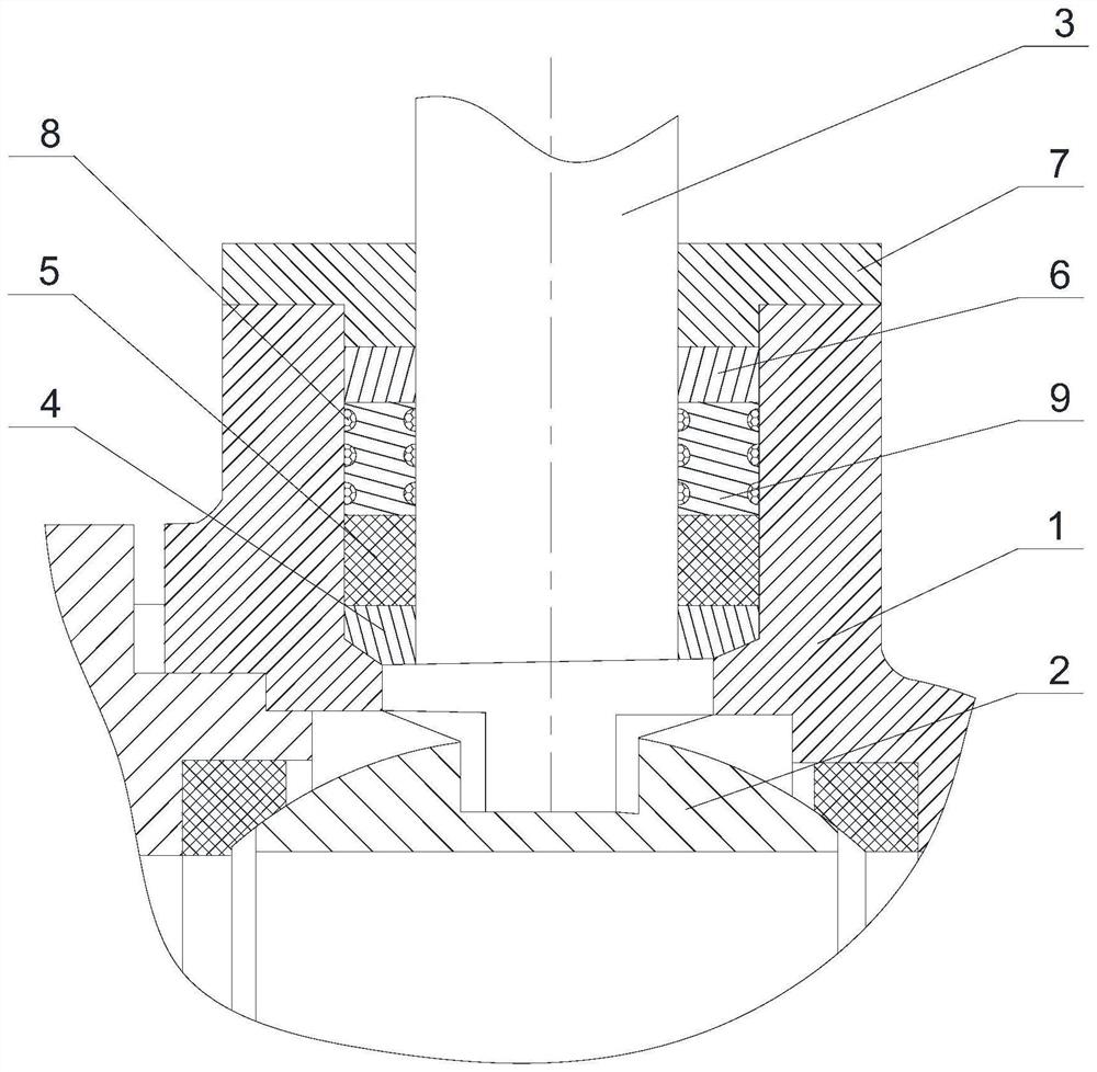
[0013] Embodiment 1: A compound sealed ball valve, which includes a ball valve seat 1, a valve core 2 is arranged inside the ball valve seat 1, one end of the valve stem 3 is fixedly connected with the valve core 2, and the other end of the valve stem 3 faces outward Extending through the valve seat of the ball valve and fixedly connected with the driving mechanism, the driving mechanism can be a wrench or an electric actuator; a sealing cavity is provided between the valve seat 1 of the ball valve with the valve stem 3 and the valve stem 3, and the sealing cavity is formed by A packing pad 4, a polytetrafluoroethylene packing layer 5, and a compression sleeve 6 are set sequentially from the inside to the outside, and a ball valve gland 7 is connected to the port of the sealing cavity, and the inner end surface of the ball valve gland 7 is in contact with the compression sleeve 6; There is also an O-ring sealing support ring assembly between the PTFE packing layer 5 and the com...


PUM

PropertyMeasurementUnit
thicknessaaaaaaaaaa

Abstract

The invention discloses a composite sealing ball valve. The composite sealing ball valve comprises a ball valve seat; a valve element is arranged in the ball valve seat; a sealing cavity is formed between the position, where a valve rod penetrates through, of the ball valve seat and the valve rod; a packing pad, a polytetrafluoroethylene packing layer and a pressing sleeve are sequentially arranged in the sealing cavity from inside to outside in a sleeved mode; and an O-shaped ring sealing supporting ring assembly is further arranged between the polytetrafluoroethylene packing layer and the pressing sleeve, and is pressed and attached to the upper portion of the polytetrafluoroethylene packing layer through the pressing sleeve. By means of the mode that the O-shaped ring sealing supportingring assembly and the polytetrafluoroethylene packing layer make up defects mutually, composite sealing is formed at the position of the valve rod, the cost is low, the structure is simple, the sealing effect is good, and maintenance and replacement are convenient.

Description

Technical field: [0001] The invention relates to a ball valve, in particular to a composite sealed ball valve. Background technique: [0002] In the process of gas transmission and distribution, ball valves play a key role in controlling gas transmission and distribution. The quality of the seal at the stem of the ball valve, the stable delivery of gas and the safe operation are all very important. Since the gas pipeline network is mostly laid underground, the valves for controlling the gas are also installed in the underground valve wells. Once the ball valve gland leaks and the gas concentration reaches 5%, an explosion will occur in case of an open flame. Therefore, no gas leakage is allowed in the valve well. Because we are located in the north, the seasons are obvious and the temperature difference is large. Especially in winter and spring, the leakage of the ball valve stem and the valve seat in the valve well will generally increase, which has become a major problem...

Claims


Application Information

Patent Timeline
Patent Type & Authority Applications(China)
IPC IPC(8): F16K41/04F16K5/06
CPCF16K5/0673F16K5/0694F16K41/046
Inventor 张俊云朝辉
Owner 呼和浩特中燃城市燃气发展有限公司
Learn More