Sunflower pollination unmanned aerial vehicle for agricultural production

A sunflower and drone technology, applied in applications, aircraft parts, plant genetic improvement, etc., can solve the problems of high pollination rate, pollen waste, low pollination rate, etc., to promote uniform distribution, improve utilization rate, and stable discharge Effect

Inactive Publication Date: 2021-01-22
徐永威
View PDF0 Cites 1 Cited by
  • Summary
  • Abstract
  • Description
  • Claims
  • Application Information

AI Technical Summary

Problems solved by technology

[0005] The purpose of the present invention is to provide a sunflower pollination drone for agricultural production with high pollination rate and low cost for the problems of low pollination rate and serious waste of pollen

Method used


Image

  • Sunflower pollination unmanned aerial vehicle for agricultural production
  • Sunflower pollination unmanned aerial vehicle for agricultural production
  • Sunflower pollination unmanned aerial vehicle for agricultural production

Examples


Embodiment 1

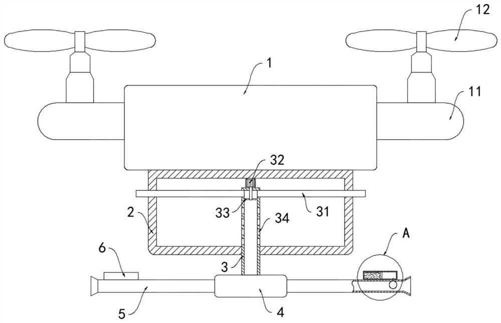
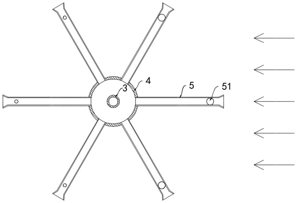
[0021] Such as Figure 1-3 As shown, a sunflower pollination UAV for agricultural production includes a body 1, four wings 11 are installed on the side wall of the body 1, propellers 12 are installed on the upper ends of the four wings 11, and the lower surface of the body 1 The pollen storage box 2 is installed, and the pollen storage box 2 is fixedly installed with a vertically arranged mixed flow tube 3. The mixed flow tube 3 is provided with a powder feeding mechanism, and the powder feeding mechanism includes two suction pipes fixedly connected to the upper end of the mixed flow tube 3. 31. The other end of the suction pipe 31 runs through the side wall of the pollen storage box 2 and extends to the outside of the pollen storage box 2. A motor 32 is installed on the inner top surface of the pollen storage box 2. A fan 33 is arranged in the mixed flow tube 3. The motor The output shaft of 32 extends into the mixed flow cylinder 3 and is fixedly connected with the fan 33 . ...

Embodiment 2

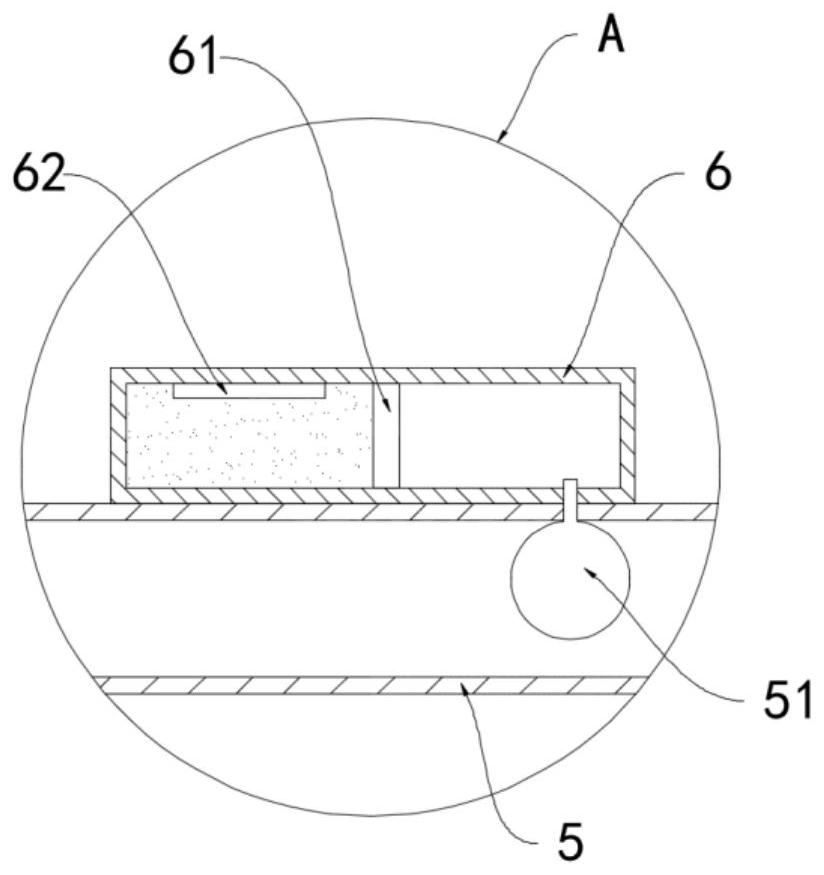
[0026] The difference between this embodiment and Embodiment 1 lies in that the thermal expansion and contraction medium is silver bromide and copper dioxide powder.

[0027] In this example, silver bromide can be quickly decomposed into bromine gas and simple silver under the catalysis of copper dioxide and light, and the reaction equation is 2AgBr==2Ag+Br 2 , generates gas, expands in volume, reverses reaction in the absence of light, regenerates silver bromide, shrinks in volume, is more sensitive to light, and is not affected by the temperature of the external environment, making the opening and closing of the pollination pipeline 5 more sensitive and The work is stable, and the effective utilization rate of pollen is further improved.


PUM


Abstract

The invention belongs to the technical field of agricultural unmanned aerial vehicles, and particularly relates to a sunflower pollination unmanned aerial vehicle for agricultural production. The sunflower pollination unmanned aerial vehicle comprises a vehicle body, four wings are installed on the side wall of the vehicle body, propellers are installed at the upper ends of the four wings, and a pollen storage box is installed on the lower surface of the vehicle body; a vertically-arranged flow mixing cylinder is fixedly installed in the pollen storage box, a pollen feeding mechanism is arranged on the flow mixing cylinder, the lower end of the flow mixing cylinder penetrates through the bottom surface of the pollen storage box and is fixedly communicated with a flow dividing box, and theside wall of the flow dividing box is fixedly communicated with a plurality of pollination pipelines which are distributed in a circumferential array manner; and an expansion ball is fixedly connectedto the inner side wall of each pollination pipeline, and a transparent sealing cylinder communicating with the corresponding expansion ball is installed on the side wall of each pollination pipeline.By means of the sunflower pollination unmanned aerial vehicle, opening of the pollination pipelines facing sunflower flowers and the closing of the pollination pipelines back to the sunflower flowerscan be automatically regulated and controlled, so that the pollination rate is greatly improved, the pollen waste is reduced, and the cost is reduced.

Description

technical field [0001] The invention belongs to the technical field of agricultural drones, in particular to a sunflower pollination drone for agricultural production. Background technique [0002] With the rapid development of the economy, it has brought about serious environmental damage and the reduction of biological resources. The harsh living environment will lead to fewer and fewer bees, and a serious decline in plant pollination, which affects the growth of crops including sunflower, Rice and apples will even lead to a global crop crisis. Therefore, in the existing technology, drone pollination will be used to increase the pollination rate of crops to increase production. [0003] When the existing pollination UAV is working, it sprays pollen around through multiple pollination pipes arranged in a circumferential direction, or sprays pollen in a fixed direction through a single pollination pipe. When pollinating sunflower crops, it is necessary to continuously chang...

Claims


Application Information

Patent Timeline
Patent Type & Authority Applications(China)
IPC IPC(8): A01H1/02B64D1/18
CPCB64D1/18
Inventor 徐永威柏丹丹
Owner 徐永威
Why Eureka
Try Eureka