Diaphragm gluing mechanism for lithium ion battery and operation method thereof
What is Al technical title?
Al technical title is built by PatSnap Al team. It summarizes the technical point description of the patent document.
A lithium-ion battery and diaphragm technology, which is applied to battery components, circuits, coatings, etc., can solve problems such as lowering the yield of diaphragm coating, unevenness of the amount of glue sprayed, and lower quality of the diaphragm, so as to avoid coating Unbalanced glue, improving the yield rate, and improving the quality of the effect
Pending Publication Date: 2021-01-22
广东嘉尚新能源科技有限公司
View PDF10 Cites 0 Cited by
Summary
Abstract
Description
Claims
Application Information
AI Technical Summary
This helps you quickly interpret patents by identifying the three key elements:
Problems solved by technology
Method used
Benefits of technology
Problems solved by technology
For the lithium battery series, because the electrolyte is an organic solvent system, a diaphragm material resistant to organic solvents is required. Generally, a high-strength thin-film polyolefin porous film is used. In the process of manufacturing and using the diaphragm, the diaphragm is often required Carry out gluing treatment to make the required diaphragm, so in the process of gluing the diaphragm, it is often necessary to use a diaphragm gluing mechanism to facilitate better gluing treatment of the diaphragm, but the traditional gluing mechanism, in the process of Summary of the process of spraying the diaphragm Due to the difference in the amount of glue sprayed, the diaphragm glue is uneven, which reduces the quality of the diaphragm. In the process of using the diaphragm spraying mechanism, in order to facilitate the processing of the film, the entrance and exit of the film are usually for the convenience of work. It is opened by personnel to carry out the membrane penetration process, and the opening of the membrane inlet and outlet is easy to cause dust to enter the box, make the dust contact with the diaphragm, and cause the dust to remain on the diaphragm, thereby reducing the yield of diaphragm glue coating.
Method used
Image
Click on the blue label to locate the original text in one second.
Reading with bidirectional positioning of images and text.
Examples
Embodiment Construction
[0028] The following will clearly and completely describe the technical solutions in the embodiments of the present invention with reference to the accompanying drawings in the embodiments of the present invention. Obviously, the described embodiments are only some, not all, embodiments of the present invention. Based on the embodiments of the present invention, all other embodiments obtained by persons of ordinary skill in the art without making creative efforts belong to the protection scope of the present invention.
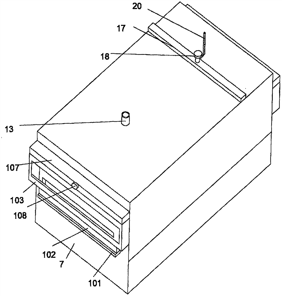
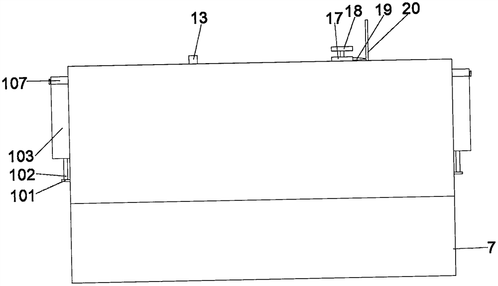
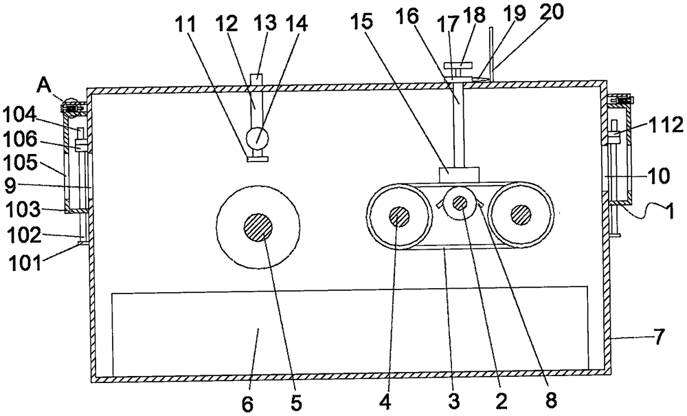
[0029] see Figure 1-7, the present invention provides a technical solution: a separator gluing mechanism for lithium-ion batteries, including a dustproof assembly 1, a first roller 2, a conveyor belt 3, a second roller 4, a third roller 5, Collection box 6, box body 7, inclined block 8, feed inlet 9, discharge outlet 10, nozzle 11, connecting column 12, transport pipe 13, discharge pipe 14, scraper 15, connecting rod 16, retaining rod 17, screw 18. Pointer 1...
PUM
Abstract
The invention discloses a diaphragm gluing mechanism for a lithium ion battery and an operation method thereof. The diaphragm gluing mechanism comprises a dustproof assembly, a first roller, a conveying belt, a second roller, a third roller, a collecting box, a box body, an inclined block, a feeding opening, a discharging opening, a spraying head, a connecting column, a conveying pipe, a discharging pipe, a scraping plate, a connecting rod, a stop rod, a screw rod, a pointer and a graduated scale rod. According to the diaphragm gluing mechanism, the distance between the scraping plate and a diaphragm can be advantageously adjusted by using the installed screw rod, so that glue scraping treatment is conveniently conducted according to the diaphragms of different specifications, the application range of the diaphragm gluing mechanism is enlarged, meanwhile, glue on the diaphragms is scraped away through the installed scraping plate, unbalanced diaphragm gluing is avoided, therefore the quality of the diaphragms is improved, redundant glue is advantageously collected by using the installed collecting box, meanwhile, the entering amount of dust entering the box body is effectively reduced by using the installed dustproof assembly, and therefore the yield of diaphragm gluing is increased.
Description
technical field [0001] The invention relates to the technical field of a diaphragm gluing mechanism, in particular to a diaphragm gluing mechanism for a lithium-ion battery and an operating method thereof. Background technique [0002] In the structure of lithium batteries, the separator is one of the key inner components. The performance of the separator determines the interface structure and internal resistance of the battery, which directly affects the capacity, cycle and safety performance of the battery. A separator with excellent performance plays an important role in improving the overall performance of the battery. The main function of the diaphragm is to separate the positive and negative electrodes of the battery, prevent the two electrodes from contacting and short circuit, and also have the function of allowing electrolyte ions to pass through. The separator material is non-conductive, and its physical and chemical properties have a great influence on the perfor...
Claims
Application Information
Patent Timeline
Application Date:The date an application was filed.
Publication Date:The date a patent or application was officially published.
First Publication Date:The earliest publication date of a patent with the same application number.
Issue Date:Publication date of the patent grant document.
PCT Entry Date:The Entry date of PCT National Phase.
Estimated Expiry Date:The statutory expiry date of a patent right according to the Patent Law, and it is the longest term of protection that the patent right can achieve without the termination of the patent right due to other reasons(Term extension factor has been taken into account ).
Invalid Date:Actual expiry date is based on effective date or publication date of legal transaction data of invalid patent.