
Device for machining automobile front cover

A front cover, automobile technology, applied in the direction of manufacturing tools, other manufacturing equipment/tools, etc., can solve the problems of poor processing flexibility, single function, low degree of automation, etc., to achieve the effect of reducing labor, good flexibility, and good adsorption effect

Inactive Publication Date: 2021-01-22
罗仁华
View PDF7 Cites 1 Cited by
  • Summary
  • Abstract
  • Description
  • Claims
  • Application Information

AI Technical Summary

Problems solved by technology

When the driver is driving the car, the front line of sight and the reflection of natural light are very important for the driver to correctly judge the road surface and the situation ahead. The shape of the hood can effectively adjust the direction and form of the reflected light, thereby reducing the impact of light on the driver. It also has the function of preventing accidents. The engine works in a high-temperature, high-pressure and flammable environment. If there are accidents such as explosion, combustion, or leakage due to overheating or accidental damage to the original components, the engine cover can effectively block the damage caused by the explosion and play a protective role. Shield effect, at present, the processing device of the automobile hood, the function is relatively single, and the processing production needs to replace the processing equipment for alternate processing, the degree of automation is low, and the processing flexibility is relatively poor. a reasonable solution

Method used


Image

  • Device for machining automobile front cover
  • Device for machining automobile front cover
  • Device for machining automobile front cover

Examples


Embodiment Construction

[0026] The present invention will be described in further detail below in conjunction with accompanying drawing

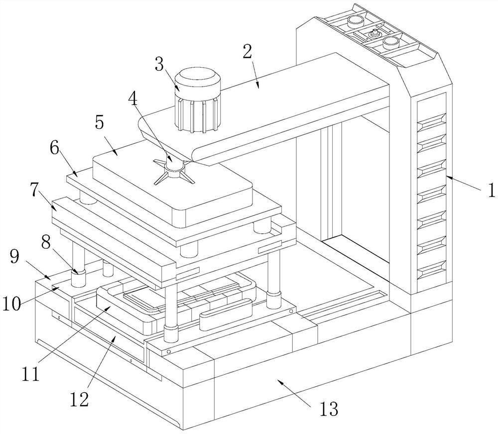
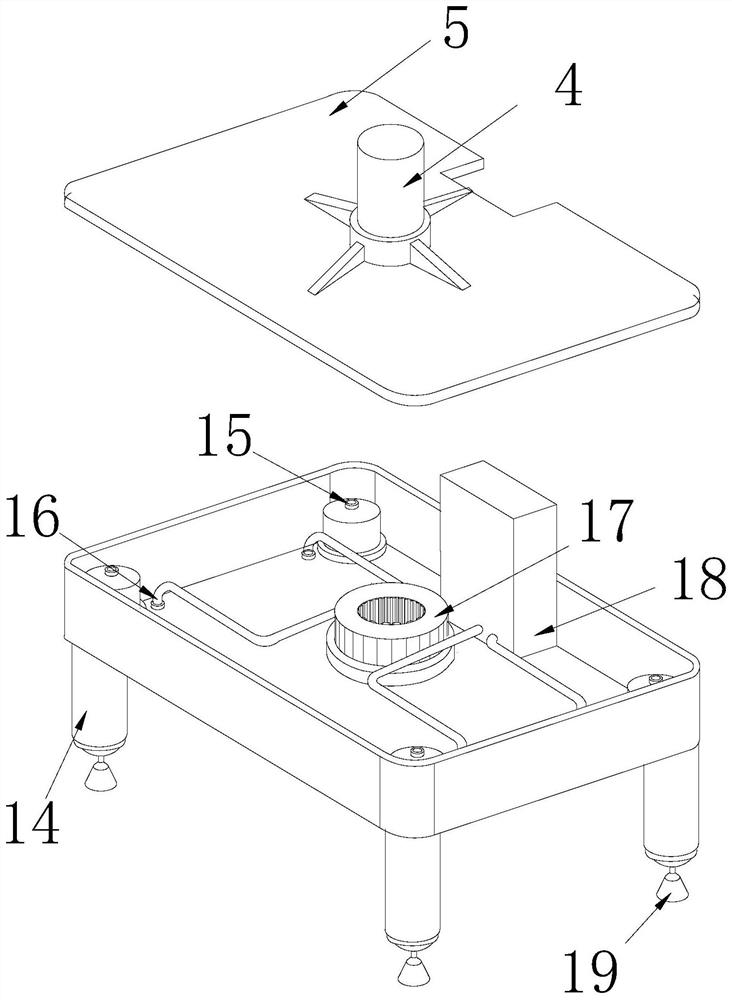
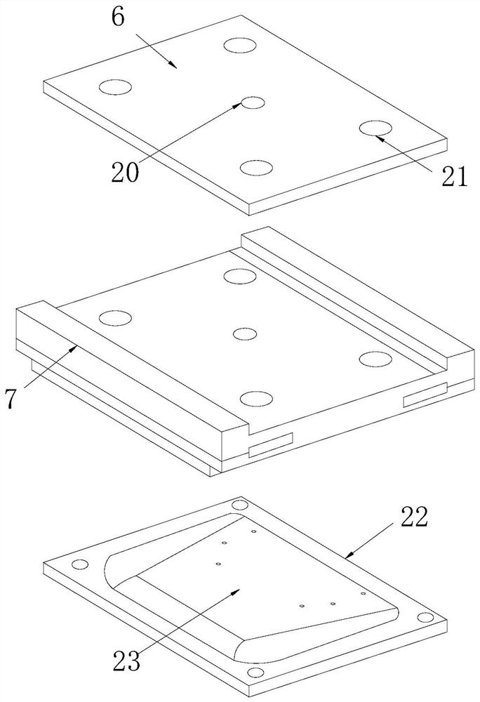
[0027] see Figure 1~6 , in an embodiment of the present invention, a device for processing an automobile front cover, comprising a supporting fixed end 1, a moving end 2 is fixedly connected to the left end of the supporting fixed end 1, and a drive motor 3 is provided on the left upper surface of the moving end 2 , the bottom end of the mobile end 2 is fixedly connected with the coupling rod 4, the bottom end of the mobile end 2 is connected with the coupling rod 4, the lower end of the coupling rod 4 is fixedly connected with the connecting end shell 5, and the bottom of the connecting end shell 5 The side is fixedly connected with a lower solid plate 6.

[0028] exist image 3 Among them, the upper surface of the lower fixed plate 6 is provided with a gear rod hole 20, and the gear rod hole 20 is symmetrical to the vertical neutral line of the lower fixed pla...


PUM


Abstract

The invention discloses a device for machining an automobile front cover, and relates to the technical field of automobile machining. According to the technical scheme, the device for machining the automobile front cover is characterized in that the left side end of a supporting fixed end is fixedly connected with a movable end, a driving motor is arranged on the upper surface of the left side ofthe movable end, the bottom end of the movable end is fixedly connected with a coupling rod, the bottom end of the movable end is connected with the coupling rod, the tail end of the lower side of thecoupling rod is fixedly connected with a connecting end shell, the bottom side face of the connecting end shell is fixedly connected with a lower fixing plate, a lower pressing table is arranged under the lower fixing plate, the boundary dimension of the lower fixing plate is matched with that of the lower pressing table, an upper die plate is fixed to the bottom end of the lower pressing table,the upper die plate is in threaded connection with the lower pressing table, and a die groove is formed in the upper surface of the upper die plate. According to the structure, a good adsorption effect is achieved through the piston type adsorption structure, the gravity center balance of an adsorption piece is convenient to control, meanwhile, up-down displacement can be conducted to a certain degree, and good flexibility is achieved.

Description

technical field [0001] The invention relates to the technical field of automobile processing, in particular to a device for processing an automobile front cover. Background technique [0002] Made of rubber foam cotton and aluminum foil materials, while reducing engine noise, it can simultaneously isolate the heat generated by the engine when it is working, effectively protect the paint on the surface of the engine cover, prevent aging, protect the engine and surrounding pipeline accessories, etc. . When the driver is driving the car, the front line of sight and the reflection of natural light are very important for the driver to correctly judge the road surface and the situation ahead. The shape of the hood can effectively adjust the direction and form of the reflected light, thereby reducing the impact of light on the driver. It also has the function of preventing accidents. The engine works in a high-temperature, high-pressure and flammable environment. If there are acci...

Claims


Application Information

Patent Timeline
IPC IPC(8): B23P23/04
CPCB23P23/04
Inventor 罗仁华
Owner 罗仁华
Learn More