
Multi-stage low-temperature centrifugal pump provided with built-in motor

A built-in, centrifugal pump technology, applied in the field of centrifugal pumps, can solve the problems of poor heat dissipation performance, high core loss of pump motor, large calorific value, etc., achieve good heat dissipation effect, good sealing effect, and meet low temperature effects

Active Publication Date: 2021-01-22
JIANGSU UNIV
View PDF5 Cites 0 Cited by
  • Summary
  • Abstract
  • Description
  • Claims
  • Application Information

AI Technical Summary

Problems solved by technology

The pump body of the existing cryogenic pump is separated from the motor, and the rotating shaft of the pump body protrudes from the pump casing to connect with the motor. The rotating shaft and the casing are sealed by a dynamic sealing device. The requirements for sealing materials are very high; at present, the core loss of the pump motor is high and the heat generation is large. The higher the motor speed, the greater the heat generation. Usually, the air cooling device is used for cooling, which not only increases the volume of the pump, but also has poor heat dissipation performance.

Method used


Image

  • Multi-stage low-temperature centrifugal pump provided with built-in motor
  • Multi-stage low-temperature centrifugal pump provided with built-in motor
  • Multi-stage low-temperature centrifugal pump provided with built-in motor

Examples


Embodiment Construction

[0035] Embodiments of the present invention are described in detail below, and examples of the illustrated embodiments are illustrated in the drawings, wherein like or similar reference numerals designate the same or similar elements or elements having the same or similar functions throughout. The embodiments described below by referring to the figures are exemplary and are intended to explain the present invention and should not be construed as limiting the present invention.

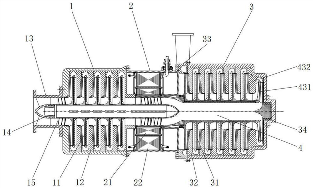
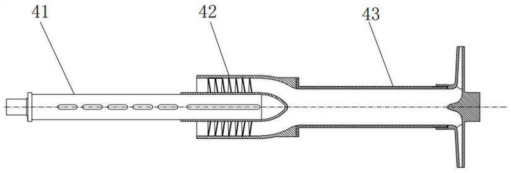
[0036] Such as figure 1 The multistage low-temperature centrifugal pump with a built-in motor shown includes a front casing 1, a motor casing 2, and a rear casing 3. The front casing 1 is provided with a positive impeller 11 and positive guide vanes 12, and the motor casing 2 is provided with a motor rotor 21. and the electronic stator 22, the rear shell 3 is provided with an anti-impeller 31 and an anti-guide vane 32; the front shell 1 is fixed on one side of the motor shell 2, the rear shell 3 is fix...


PUM


Abstract

The invention provides a multi-stage low-temperature centrifugal pump provided with a built-in motor. The multi-stage low-temperature centrifugal pump comprises a front shell, a motor shell and a backshell; a forward impeller and a forward guide vane are arranged in the front shell; the motor is arranged in the motor shell; a reverse impeller and a reverse guide vane are arranged in the back shell; the motor shell is located between the front shell and the back shell; an inlet horn pipe is arranged at the end of the front shell; an outlet volute is arranged between the back shell and the motor shell; the forward impeller, a motor rotor and the reverse impeller are connected in series through a rotating shaft assembly; the motor rotor is directly connected with the rotating shaft assemblyfrom the middle to drive the rotating shaft assembly to rotate so as to drive the forward impeller, the reverse impeller and an inducer to rotate. A low-temperature liquid enters a pump body from theinlet horn pipe, is pressurized by the forward impeller and the reverse impeller and is sprayed out of the outlet volute. According to the pump, the motor is arranged internally and is cooled throughthe low-temperature liquid, the overall sealing performance is good, the size is small, the weight is light, the structure is compact, and the pump is particularly applicable to conveying of low-temperature volatile liquids.

Description

technical field [0001] The invention belongs to the field of centrifugal pumps, in particular to a multistage low-temperature centrifugal pump with a built-in motor. Background technique [0002] In the transportation of cryogenic liquids, such as the mining and transportation of LNG (liquefied natural gas), cryogenic pumps are required. The pump body of the existing cryogenic pump is separated from the motor, and the rotating shaft of the pump body protrudes from the pump casing to connect with the motor. The requirements for sealing materials are very high; at present, the core loss of the pump motor is high, and the heat generation is large. The higher the motor speed, the more heat is generated. Usually, the air cooling device is used for cooling, which not only increases the volume of the pump, but also has poor heat dissipation performance. With the development of cryogenic liquid-related industries, the application range and performance requirements of cryopumps have...

Claims


Application Information

Patent Timeline
Patent Type & Authority Applications(China)
IPC IPC(8): F04D17/12F04D25/06F04D29/10F04D29/053F04D29/44F04D29/056F04D29/08F04D29/051H02K9/19
CPCF04D17/12F04D25/0606F04D29/102F04D29/051F04D29/053F04D29/441F04D29/056F04D29/083H02K9/19
Inventor 龙云安策朱荣生钟锦情
Owner JIANGSU UNIV
Learn More