Supercharge Your Innovation With Domain-Expert AI Agents!

Refractive Index Sensing Device Based on Few-Mode Silicon Nitride Microring Resonator

A technology of a silicon nitride microring resonator and a silicon nitride microring resonator is applied in the field of refractive index sensing and can solve the problems of high detection limit and narrow dynamic range.

Active Publication Date: 2021-10-26
SHANGHAI JIAOTONG UNIV
View PDF0 Cites 0 Cited by
  • Summary
  • Abstract
  • Description
  • Claims
  • Application Information

AI Technical Summary

Problems solved by technology

[0002] The refractive index sensor is a device that can sense the change of the refractive index near the waveguide and convert it into a change of the output optical properties. According to the different sensing principles, it is divided into intensity detection and wavelength detection. The former is by detecting the transmission spectrum. Before and after the change of refractive index, the change of light intensity at the same wavelength is used for sensing and detection. The microring waveguide used in this method has a high quality factor, but since this method can only be detected near the resonance peak, the detection limit high, narrow dynamic range

Method used


Image

  • Refractive Index Sensing Device Based on Few-Mode Silicon Nitride Microring Resonator
  • Refractive Index Sensing Device Based on Few-Mode Silicon Nitride Microring Resonator
  • Refractive Index Sensing Device Based on Few-Mode Silicon Nitride Microring Resonator

Examples


Embodiment Construction

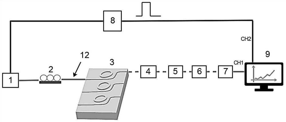
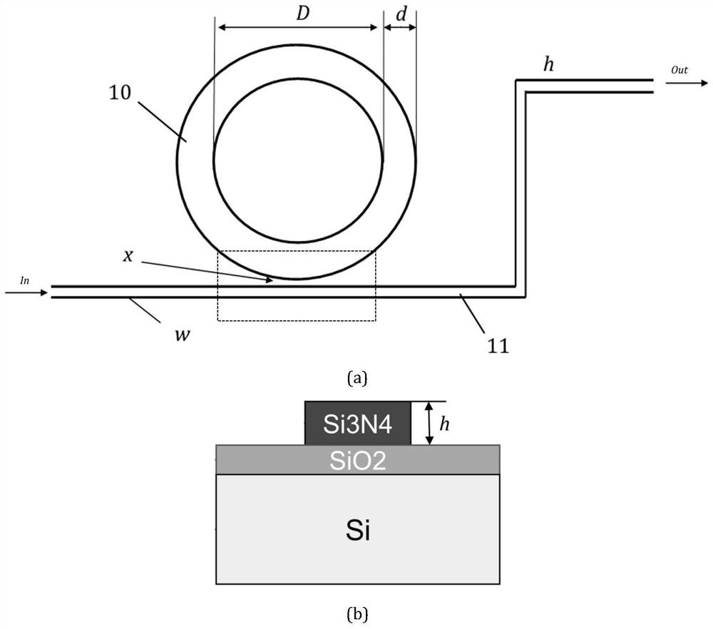
[0019] Such as figure 2 (a) and figure 2 As shown in (b), it is the few-mode silicon nitride microring resonator 3 involved in this embodiment, including: several waveguide units arranged side by side, each unit is composed of a single single-mode straight waveguide 10 for input and output and It consists of a single few-mode ring waveguide 11 for resonance, wherein: the straight waveguide and the ring waveguide in the unit are placed on the same plane and do not touch each other, the straight waveguides between the units are parallel to each other, and the two ends of a single single-mode straight waveguide are respectively as input and output.

[0020] The single single-mode straight waveguide is a Z-shaped structure.

[0021] Such as figure 2 As shown in (b), the few-mode silicon nitride microring resonator 3 is sequentially arranged on the silicon substrate and the silicon dioxide layer.

[0022] The width of the single-mode straight waveguide is 0.6 μm-1.5 μm, and ...


PUM

PropertyMeasurementUnit
widthaaaaaaaaaa
thicknessaaaaaaaaaa
radiusaaaaaaaaaa

Abstract

A refractive index sensing device based on a few-mode silicon nitride microring resonator, the few-mode silicon nitride microring resonator includes several waveguide units arranged side by side, each unit consists of a single The straight waveguide and a single few-mode ring waveguide for resonance are composed of the straight waveguide and the ring waveguide in the unit on the same plane without contact, the straight waveguides between the units are parallel to each other, and the two ends of a single single-mode straight waveguide as input and output respectively. A single straight waveguide and a single ring waveguide structure of an all-pass microring resonator support at least one mode, which can generate resonance peaks corresponding to the fundamental mode and higher-order modes in the transmission spectrum, and the optical fields of different modes have different drifts for refractive index changes , so this characteristic can be used for the measurement of refractive index sensing.

Description

technical field [0001] The invention relates to a technology in the field of refractive index sensing, in particular to a refractive index sensor which adopts a few-mode microring resonator structure manufactured by an SOI method and uses a wavelength detection method for sensing and detection. Background technique [0002] The refractive index sensor is a device that can sense the change of the refractive index near the waveguide and convert it into a change of the output optical properties. According to the different sensing principles, it is divided into intensity detection and wavelength detection. The former is by detecting the transmission spectrum. Before and after the change of refractive index, the change of light intensity at the same wavelength is used for sensing and detection. The microring waveguide used in this method has a high quality factor, but since this method can only be detected near the resonance peak, the detection limit High, narrow dynamic range. ...

Claims


Application Information

Patent Timeline
Patent Type & Authority Patents(China)
IPC IPC(8): G01N21/41G01N21/01
CPCG01N21/01G01N21/4133
Inventor 何祖源马麟邱辞源刘明慧庞拂飞
Owner SHANGHAI JIAOTONG UNIV
Features
  • R&D
  • Intellectual Property
  • Life Sciences
  • Materials
  • Tech Scout
  • Unparalleled Data Quality
  • Higher Quality Content
  • 60% Fewer Hallucinations
Learn More