Cutting tool wear in-situ measurement device and method for manufacturing Internet of Things

A technology for manufacturing the Internet of Things and cutting tools. It is applied in the direction of manufacturing tools, measuring/indicating equipment, and metal processing machinery parts. It can solve problems such as low detection efficiency and positioning errors of disassembling and assembling cutting tools, and improve production efficiency and production quality. , Guaranteed parallelism and reduced production costs

Pending Publication Date: 2021-01-26
NANJING UNIV OF AERONAUTICS & ASTRONAUTICS
View PDF6 Cites 9 Cited by
  • Summary
  • Abstract
  • Description
  • Claims
  • Application Information

AI Technical Summary

Problems solved by technology

[0003] The cutting tool wear monitoring method is divided into indirect detection method and direct detection method. The indirect detection method generally judges the current state of the cutting tool by monitoring the cutting force, vibration, acoustic emission and other sensor signals directly related to the wear amount of the cutting tool. Wear state, this method has a lot of randomness, and can only qualitatively detect the wear state of the cutting tool; the direct detection method usually refers to the detection

Method used


Image

  • Cutting tool wear in-situ measurement device and method for manufacturing Internet of Things
  • Cutting tool wear in-situ measurement device and method for manufacturing Internet of Things
  • Cutting tool wear in-situ measurement device and method for manufacturing Internet of Things

Examples


Embodiment 1

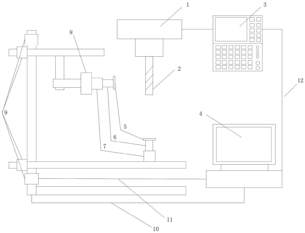
[0056] Such as figure 1 As shown, it is an embodiment of an on-site measurement device for cutting tool wear used in manufacturing the Internet of Things, which includes an industrial computer (4), which is the core processing unit of the system, and includes a camera communication module and a machine tool communication module inside , image processing and wear calculation module.

[0057] It also includes a CNC machine tool spindle (1). A tool (2) is installed on the CNC machine tool spindle (1). The tool (2) is the object to be detected in this embodiment. The tool (2) has a side edge and a bottom edge. The CNC machine tool The main shaft (1) can drive the tool (2) to rotate or to reciprocate and linearly move in the Z-axis direction.

[0058] It also includes a telecentric lens (6) and a CCD industrial camera (7), which are in two groups and are respectively facing the side edge and the bottom edge of the cutter (2), that is, between the two groups of CCD industrial camer...

Embodiment 2

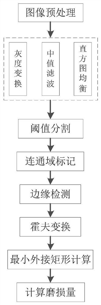
[0064] Such as figure 2 As shown, it is a flow chart of a measurement method for an in-situ measurement device for cutting tool wear used in manufacturing the Internet of Things, which mainly includes the following steps:

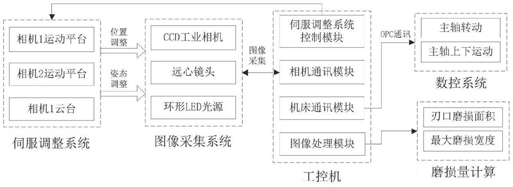
[0065] S1. Adjust the hardware and software configuration of the image in-position perception system; calibrate the internal and external parameters of the camera used, adjust the focal length of the lens and the intensity of the light source to ensure a clear and undistorted image. It mainly includes the following two steps:

[0066] S11. respectively calibrate the internal and external parameters of the two CCD industrial cameras (7), the focal lengths of the two telecentric lenses (6) and the intensity and direction of the two ring-shaped LED light sources (5), to ensure that a clear and distortion-free image can be obtained;

[0067] S12. Configure the shutter time and resolution of the two CCD industrial cameras (7) through the camera communication b...


PUM


Abstract

The invention provides a cutting tool wear in-situ measurement device and method for the manufacturing Internet of Things, which achieve in-situ measurement of cutting tool wear in the manufacturing Internet of Things, and thus improve the efficiency and the accuracy of tool wear measurement. The measurement device comprises a numerical control machine tool spindle, a cutter, telecentric lenses, CCD industrial cameras, and an industrial personal computer, wherein the cutter is a to-be-detected object and is installed on the numerical control machine tool spindle, the cutter is provided with aside edge and a bottom edge, the numerical control machine tool spindle drives the cutter to rotate or reciprocate linearly in the Z-axis direction, the two groups of telecentric lenses and CCD industrial cameras face the side edge and the bottom edge of the cutter correspondingly and are used for photographing the cutter, the telecentric lenses and the CCD industrial cameras can also reciprocatelinearly in the X-axis direction and the Z-axis direction, the industrial personal computer comprises a camera communication module, a machine tool communication module and an image processing and abrasion loss calculation module, and the industrial personal computer is used for controlling actions of the CCD industrial cameras and the numerical control machine tool spindle and can process pictures shot by the CCD industrial cameras.

Description

technical field [0001] The invention relates to the technical field of CNC machine tool wear measurement, mainly a method, system and device for measuring tool wear, and in particular to an on-site measurement device and method for cutting tool wear used in manufacturing the Internet of Things. Background technique [0002] In the metal cutting process, as a part in direct contact with the workpiece, cutting tool wear is a ubiquitous and inevitable phenomenon, and it continues to increase with the increase of processing time. With the rapid development of aerospace technology, higher requirements are put forward for the material, structure and machining accuracy of parts. Aerospace difficult-to-machine materials have the characteristics of complex structure and large removal amount. Therefore, more requirements are put forward for cutting tool wear measurement. high demands. According to industrial statistics, the proportion of parts scrapped and machine tool downtime due t...

Claims


Application Information

Patent Timeline
IPC IPC(8): B23Q17/09
CPCB23Q17/09B23Q17/0957
Inventor 杨文安刘伟超
Owner NANJING UNIV OF AERONAUTICS & ASTRONAUTICS
Why Eureka
Try Eureka