Electrical synergistic heat supply reforming reaction system

A reforming reaction and heating system technology, applied in the chemical industry, can solve the problems that limit the continuous and stable operation of chemical equipment, achieve the effect of reducing material selection requirements, avoiding ultra-high temperature areas, and reducing the generation of NOx gas

Active Publication Date: 2021-01-26
庄焱法
View PDF7 Cites 8 Cited by
  • Summary
  • Abstract
  • Description
  • Claims
  • Application Information

AI Technical Summary

Problems solved by technology

However, the intermittency of solar energy, wind energy and hydropower severely limits the continuous and stable operation of chemical plants.

Method used


Image

  • Electrical synergistic heat supply reforming reaction system
  • Electrical synergistic heat supply reforming reaction system
  • Electrical synergistic heat supply reforming reaction system

Examples


Embodiment 1

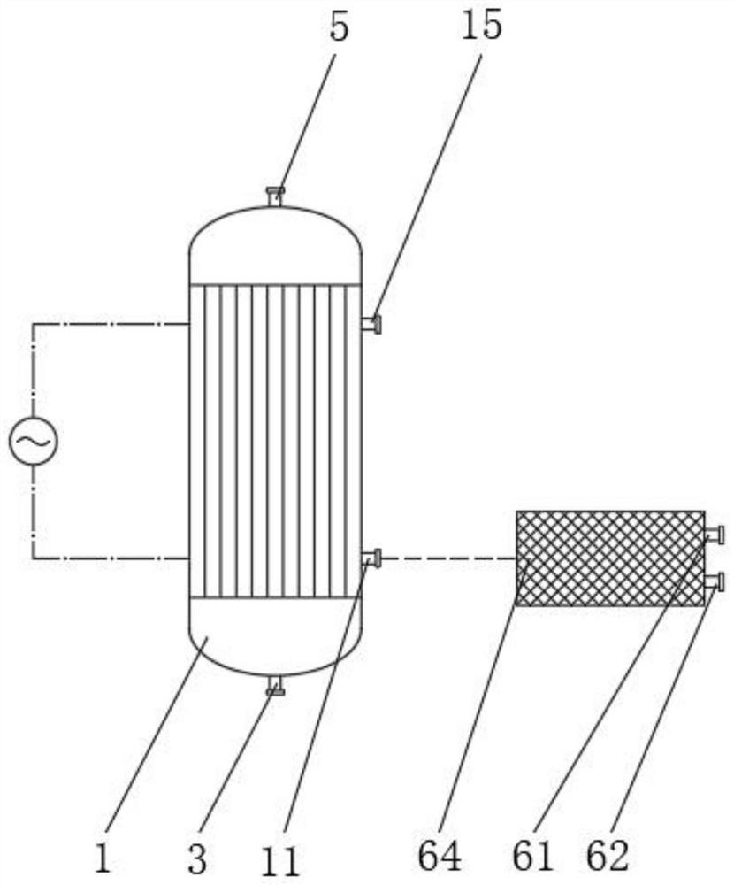
[0058] Example 1: Externally supplied flue gas single-stage induction heating reforming reaction system

[0059] The reforming reactor 1 used by the external flue gas single-stage induction heating reforming reaction system, the high-temperature flue gas transported from the outside to the inside of the reactor and the induction eddy current caused by the single-stage induction coil 52 cooperate to form the reforming reactor 1 heating. To achieve this purpose, the present invention lists the following embodiment.

[0060] Implementation structure:

[0061] Such as Figure 4 and Figure 9 As shown, a plurality of bayonet tubes consisting of the outer tube 22 of the conversion tube and the inner tube 23 of the conversion tube are arranged in an orderly manner around the central flue gas tube 26 . The annular gap between the outer tube 22 of the reforming tube and the inner tube 23 of the reforming tube is filled with the reforming catalyst layer 2 , and the inner tube 23 of ...

Embodiment 2

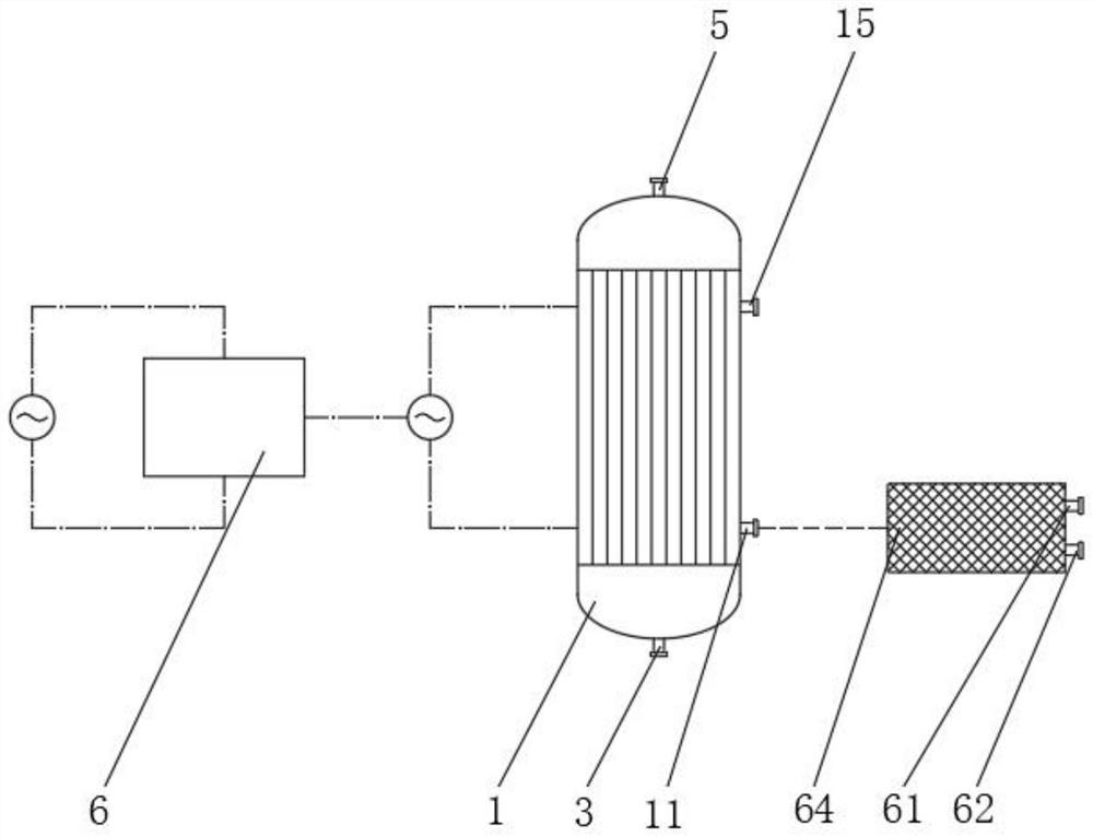
[0071] Example 2: Internally supplied flue gas single-stage induction heating reforming reaction system

[0072] The reforming reactor 1 used in the flue gas single-stage induction heating reforming reaction system, the high-temperature flue gas generated by catalytic combustion inside the reactor and the induction eddy current caused by the single-stage induction coil 52 cooperate to provide heat for the reforming reactor 1 . To achieve this purpose, the present invention lists the following embodiment.

[0073] Implementation structure:

[0074] Such as Figure 5 and Figure 9As shown, a plurality of bayonet tubes consisting of the outer tube 22 of the conversion tube and the inner tube 23 of the conversion tube are arranged in an orderly manner around the central flue gas tube 26 . The annular gap between the outer tube 22 of the reforming tube and the inner tube 23 of the reforming tube is filled with the reforming catalyst layer 2 , and the inner tube 23 of the reform...

Embodiment 3

[0083] Example 3: Internally supplied flue gas multi-stage induction heating reforming reaction system

[0084] In the reforming reactor 1 used by the flue gas multi-stage induction heating reforming reaction system, the high-temperature flue gas generated by catalytic combustion inside the reactor and the induction eddy current caused by the multi-stage induction coil 52 cooperate to provide heat for the reforming reactor 1 . To achieve this purpose, the present invention lists the following embodiment.

[0085] Implementation structure:

[0086] like Figure 6 and Figure 9 As shown, a plurality of bayonet tubes consisting of the outer tube 22 of the conversion tube and the inner tube 23 of the conversion tube are arranged in an orderly manner around the central flue gas tube 26 . The annular gap between the outer tube 22 of the reforming tube and the inner tube 23 of the reforming tube is filled with the reforming catalyst layer 2 , and the inner tube 23 of the reforming...


PUM


Abstract

The invention discloses an electric synergistic heat supply reforming reaction system which comprises a reforming reactor and an electric synergistic heat supply device, a flue gas convection area anda reforming reaction area are formed in the reforming reactor, and the flue gas convection area comprises a flue gas distribution device and a flue gas flow guide device. According to the electric synergistic heat supply reforming reaction system, by switching the heat contribution ratio of electric heating to flue gas heating, the reactor continuously and stably operates when either electric power or fuel gas is insufficient in supply; electric synergistic heat supply is adopted, the reforming reactor is high in starting speed, and the reactor can enter a stable production state within a fewminutes; convection smoke is generated in a non-open-fire catalytic combustion mode, the combustion temperature of catalytic combustion is low, and generation of NOx gas is remarkably reduced; meanwhile, an ultra-high-temperature area in the reactor is avoided, the requirement for reactor material selection is lowered, the service life of equipment is prolonged, and wide application prospects areachieved.

Description

technical field [0001] The invention relates to the field of chemical industry, in particular to an electrical cooperative heat supply reforming reaction system. Background technique [0002] Strong endothermic reactions are often involved in chemical production processes. In order to realize this highly endothermic process, the chemical industry usually uses the direct combustion of fossil fuels for heat supply. However, the high-temperature combustion of fossil fuels will not only produce a large amount of NOx gas, but also further aggravate the emission of greenhouse gases, causing irreversible global climate problems. In order to alleviate the adverse impact of chemical production on the global climate, the scientific community has proposed the concept of electrified production in the chemical industry. The use of electricity generated by renewable energy to provide energy for chemical industry production not only alleviates global climate problems, but also provides t...

Claims


Application Information

Patent Timeline
Patent Type & Authority Applications(China)
IPC IPC(8): C01B3/38
CPCC01B3/384C01B2203/0233C01B2203/0811C01B2203/0838C01B2203/085C01B2203/0866C01B2203/1029C01B2203/1082C01B2203/1241
Inventor 龙筱焱叶家镇蒋静思冯斌
Owner 庄焱法
Why Eureka
Try Eureka