
A near-field bolometric tuner based on DC voltage biased graphene

A DC voltage and near-field radiation technology, applied in indirect heat exchangers, instruments, lighting and heating equipment, etc., can solve the problems of unavailability in actual production and excessive magnetic field strength, and achieve excellent near-field thermal radiation modulation capabilities, Easy to generate and manipulate, enhance the effect of near-field thermal radiation

Active Publication Date: 2022-03-01
HARBIN INST OF TECH
View PDF0 Cites 0 Cited by
  • Summary
  • Abstract
  • Description
  • Claims
  • Application Information

AI Technical Summary

Problems solved by technology

[0004] The purpose of the present invention is to solve the existing technical problems that the existing magnetic field actively controls the magneto-optic effect of graphene to control the near-field radiation heat exchange, the magnetic field intensity is too large, which can not be provided in actual production and the strong magnetic field will interfere with electronic components. Provide a near-field bolometric tuner based on DC voltage biased graphene

Method used


Image

  • A near-field bolometric tuner based on DC voltage biased graphene
  • A near-field bolometric tuner based on DC voltage biased graphene
  • A near-field bolometric tuner based on DC voltage biased graphene

Examples


specific Embodiment approach 1

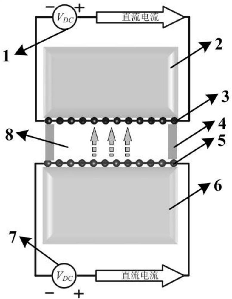
[0025] Specific implementation mode one (refer to figure 1 ): a near-field radiance tuner based on DC voltage bias graphene of the present embodiment is composed of a receiving end compound structure, a transmitting end compound structure and a spacer 4 arranged between the two, the receiving end compound structure and The spacer 4 forms a vacuum gap 8 between the composite structures of the transmitting end; the composite structure of the receiving end and the composite structure of the transmitting end are identical and symmetrically arranged with respect to the spacer 4, and the composite structure of the receiving end is controlled by a DC voltage generator at the receiving end 1. The receiving end substrate 2 and the receiving end graphene coating 3 are composed. The receiving end graphene coating 3 is plated on the lower surface of the receiving end substrate 2. The receiving end DC voltage generator 1 communicates with the receiving end graphene coating 3 through wires a...

specific Embodiment approach 2

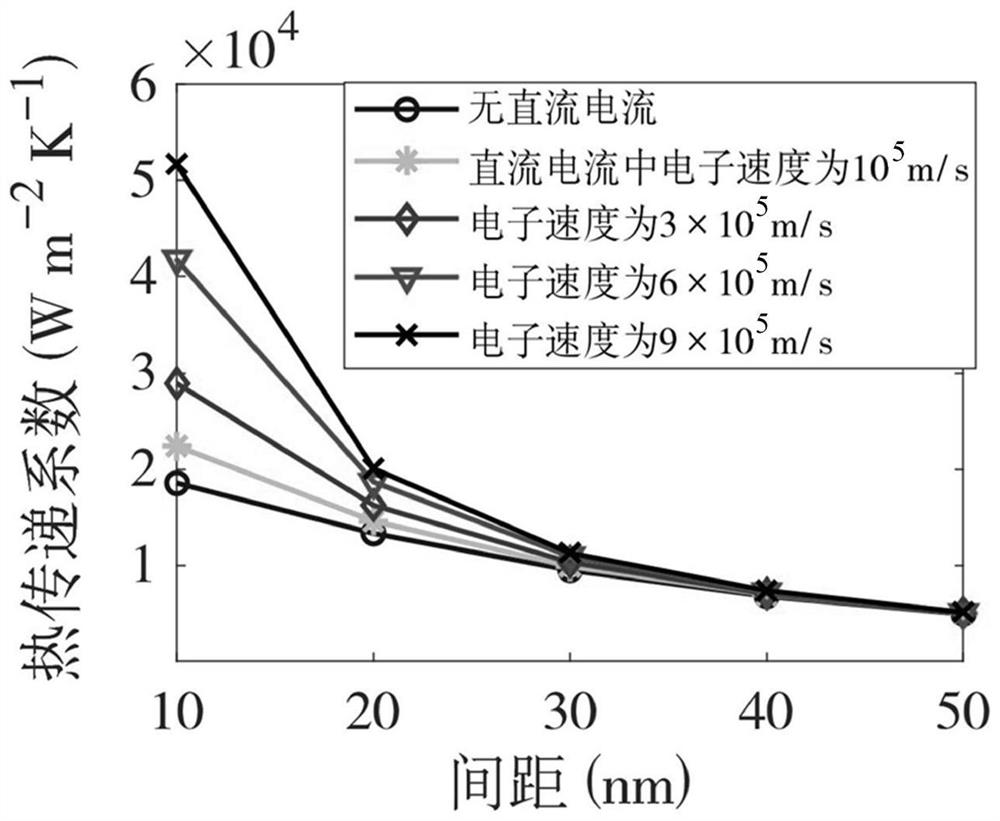
[0031] Specific embodiment 2: The difference between this embodiment and specific embodiment 1 is that the vertical distance between the composite structure at the receiving end and the composite structure at the transmitting end is 20 nm, that is, the other steps and parameters described in the height of the spacer 4 are related to the specific embodiment One is the same.

specific Embodiment approach 3

[0032] Embodiment 3: The difference between this embodiment and Embodiment 1 is that the vertical distance between the composite structure at the receiving end and the composite structure at the transmitting end is 30 nm, that is, the other steps and parameters described in the height of the spacer 4 are related to the specific embodiment. One is the same.


PUM

PropertyMeasurementUnit
thicknessaaaaaaaaaa
heightaaaaaaaaaa

Abstract

A near-field bolometric tuner based on DC voltage biased graphene. The invention belongs to the field of thermal tuners. The purpose of the present invention is to solve the existing technical problems of using magnetic field to actively control the magneto-optic effect of graphene to control near-field radiation heat transfer because the magnetic field strength is too large to be available in actual production and the strong magnetic field will interfere with electronic components. A near-field radiant heat tuner based on DC voltage bias graphene of the present invention is composed of a receiving end composite structure, a transmitting end composite structure and a spacer arranged between the two, and the receiving end composite structure is composed of a receiving end The DC voltage generator, the receiving end substrate and the receiving end graphene coating are composed; the transmitting end composite structure is composed of the transmitting end DC voltage generator, the transmitting end substrate and the transmitting end graphene coating. The tuner of the invention can have a strong adjustment effect on the near-field radiation heat transfer capability. At the same time, regulation based on direct current does not interfere with the rest of the electronic components.

Description

technical field [0001] The invention belongs to the field of thermal tuners, in particular to a near-field radiation thermal tuner based on DC voltage biased graphene. Background technique [0002] Compared with classical radiation, radiative heat transfer between two objects can be significantly enhanced by bringing them close to each other to provide the tunneling effect of evanescent waves. Since a large amount of heat flux is crucial in the application of thermal tuners, efforts have been made to optimize and enhance such thermal tuners by controlling various material and structural parameters. In general, since the main contribution to heat transfer comes from surface states, the general idea of ​​thermal tuners is to tune surface states in heat transfer. For example, adjusting the structure of polar dielectric materials supporting surface phonon polaritons (cBN, SiC, etc.) or adjusting the structure of systems that can support surface plasmon polaritons (metals, semic...

Claims


Application Information

Patent Timeline
Patent Type & Authority Patents(China)
IPC IPC(8): F28D21/00G02B5/00
CPCF28D21/00G02B5/008F28D2021/0019
Inventor 易红亮周承隆张勇谈和平
Owner HARBIN INST OF TECH
Learn More