AI technical title is built by PatSnap AI team. It summarizes the technical point description of the patent document.
A technology for forging equipment and steel, applied in the field of steel manufacturing, can solve the problems of safety incidents, low degree of automation, etc.
Inactive Publication Date: 2021-01-29
孙玉香
View PDF0 Cites 1 Cited by
Summary
Abstract
Description
Claims
Application Information
AI Technical Summary
This helps you quickly interpret patents by identifying the three key elements:
Problems solved by technology
Method used
Benefits of technology
Problems solved by technology
[0002] In the modern steel forging process, there are too many processes that require manual participation, the degree of automation is not high, and it is easy to cause safety incidents. This equipment solves the above problems
Method used
Image
Click on the blue label to locate the original text in one second.
Reading with bidirectional positioning of images and text.
Examples
specific Embodiment approach 1
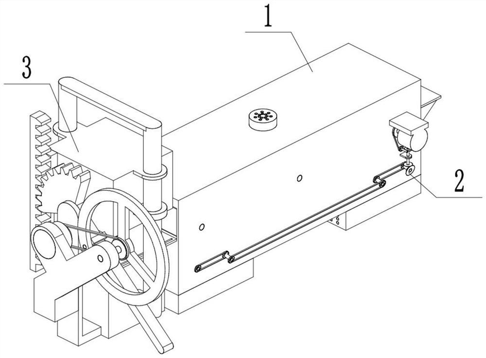
[0032] Combine below Figure 1-17 Describe this embodiment, a steel forging equipment, including a transportation assembly 1, a heating assembly 2 and a forging assembly 3, the transportation assembly 1 is connected to the heating assembly 2, and the transportation assembly 1 is connected to the forging assembly 3 .
specific Embodiment approach 2
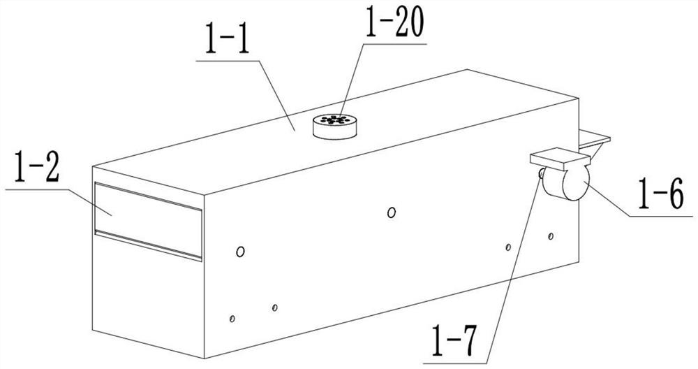
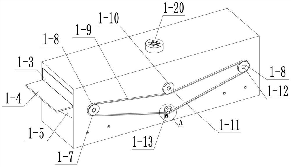
[0034] Combine below Figure 1-17Describe this embodiment, this embodiment will further explain the first embodiment, the transport assembly 1 includes a box body 1-1, a discharge door 1-2, a feed door 1-3, a feed platform 1-4, a platform Bracket 1-5, motor Ⅰ 1-6, motor Ⅰ shaft 1-7, sprocket Ⅰ 1-8, chain Ⅰ 1-9, sprocket Ⅱ 1-10, sprocket Ⅱ shaft 1-11, side shaft 1-12, Zhang Tightening sprocket 1-13, tensioning shaft 1-14, tension spring 1-15, tensioning shaft chute 1-16, toggle roller 1-17, connecting rod 1-18, hinged shaft 1-19, filter screen 1-20 and discharge inclined plate 1-21, discharge door 1-2, and feed door 1-3 are hinged with box body 1-1, and feed platform 1-4 is connected with box body 1-1, Feeding platform 1-4 is connected with platform support 1-5, platform support 1-5 is connected with box body 1-1, motor I1-6 is connected with motor I shaft 1-7, motor I1-6 is connected with box body 1-1 phase connection, the motor I axis 1-7 is rotationally connected with the ...
specific Embodiment approach 3
[0036] Combine below Figure 1-17 Describe this embodiment, this embodiment will further explain Embodiment 1, the heating assembly 2 includes a sprocket III 2-1, a chain II 2-2, a sprocket IV 2-3, a worm 2-4, a worm wheel 2-5, a worm wheel Shaft 2-6, worm gear shaft support 2-7, bevel gear Ⅰ 2-8, bevel gear Ⅱ 2-9, fan blade shaft 2-10, fan blade 2-11, baffle plate 2-12, air outlet 2-13, fan Blade shaft connecting sprocket Ⅰ 2-14, fan blade shaft connecting chain 2-15, fan blade shaft connecting sprocket Ⅱ 2-16, bottom plate with holes 2-17, combustion chamber 2-18, fuel adding door 2-19 and filter hole 2-20, motor I shaft 1-7 is connected with sprocket III 2-1, sprocket III 2-1 is connected with sprocket IV 2-3 through chain II 2-2, sprocket IV 2-3 is connected with worm 2-4 , the worm 2-4 is rotationally connected with the box 1-1, the worm 2-4 is meshed with the worm wheel 2-5, the worm wheel 2-5 is connected with the worm shaft 2-6, and the worm shaft 2-6 is connected wit...
PUM
Abstract
The invention relates to the field of steel manufacturing, in particular to steel forging and pressing equipment which solves the problems that in the modern steel forging process, too many manual participation procedures are needed, the automation degree is not high, and safety accidents are likely to be caused. Steel is placed in a transportation assembly from a feeding door. The steel is slowlyconveyed to a discharging door, in the conveying process, two sets of fan blades blow air to accelerate airflow in a box body, combustion in a combustion chamber is more sufficient, the two sets of fan blades blow air oppositely and obliquely upwards to drive airflow in the box body to flow towards the position over the box body, and heat is better transmitted to a to-be-forged piece; and after heating, the steel is conveyed to a forging and pressing platform to be forged and pressed by a forging and pressing hammer in a reciprocating mode, the forging and pressing hammer ascends slowly and descends rapidly, forging and pressing are more powerful, and the forging and pressing hammer can forge and press steel of different sizes and shapes.
Description
technical field [0001] The invention relates to the field of steel production, more specifically to a steel forging equipment. Background technique [0002] In the modern steel forging process, there are too many processes that require manual participation, the degree of automation is not high, and it is easy to cause safety incidents. This equipment solves the above problems. Contents of the invention [0003] The purpose of the present invention is to provide a steel forging equipment, which can automatically transport the steel to be forged, heat it to the forging temperature and forge the steel. [0004] The purpose of the present invention is achieved through the following technical solutions: [0005] A steel forging equipment includes a transportation assembly, a heating assembly and a forging assembly, the transportation assembly is connected with the heating assembly, and the transportation assembly is connected with the forging assembly. [0006] As a further o...
Claims
Application Information
Patent Timeline
Application Date:The date an application was filed.
Publication Date:The date a patent or application was officially published.
First Publication Date:The earliest publication date of a patent with the same application number.
Issue Date:Publication date of the patent grant document.
PCT Entry Date:The Entry date of PCT National Phase.
Estimated Expiry Date:The statutory expiry date of a patent right according to the Patent Law, and it is the longest term of protection that the patent right can achieve without the termination of the patent right due to other reasons(Term extension factor has been taken into account ).
Invalid Date:Actual expiry date is based on effective date or publication date of legal transaction data of invalid patent.

