A fiber laser welding device

A welding device, fiber laser technology, applied in the direction of laser welding equipment, welding equipment, welding equipment, etc., can solve the problems of short service life of welding machine, eye injury, single function, etc., to prolong service life, avoid cleaning trouble, avoid damage effect

Active Publication Date: 2022-04-15
GUILIN UNIV OF AEROSPACE TECH
View PDF0 Cites 0 Cited by
  • Summary
  • Abstract
  • Description
  • Claims
  • Application Information

AI Technical Summary

Problems solved by technology

[0004] The purpose of the present invention is: in order to solve the problem that the existing optical fiber laser welding device does not equip the operator with goggles for blocking the strong light, and some operators often give up wearing the goggles during operation because of the heavy weight of the goggles. Watching laser welding without barriers will cause eye injury, and the existing light laser welding device has a simple structure and single function, and cannot clean the objects after welding in time, and the welding black marks left on the objects will be damaged after a long time. It is more difficult to clean, resulting in unsightly welding traces, and the existing fiber laser welding device cannot properly dissipate heat for the welding machine after working for a long time. If the welding machine does not dissipate heat for a long time, the internal parts will be damaged due to high temperature, thus To solve the problem of short service life of the welding machine, a fiber laser welding device is provided

Method used

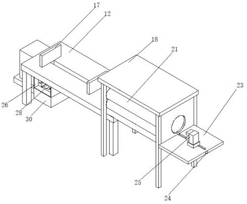
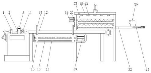
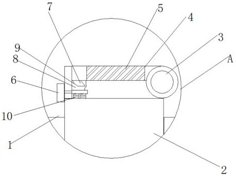

Image

  • A fiber laser welding device
  • A fiber laser welding device
  • A fiber laser welding device

Examples


Embodiment Construction

[0026] The following will clearly and completely describe the technical solutions in the embodiments of the present invention with reference to the accompanying drawings in the embodiments of the present invention. Obviously, the described embodiments are only some, not all, embodiments of the present invention. Based on the embodiments of the present invention, all other embodiments obtained by persons of ordinary skill in the art without making creative efforts belong to the protection scope of the present invention.

[0027] In the description of the present invention, it should be noted that the terms "center", "upper", "lower", "left", "right", "vertical", "horizontal", "inner", "outer" etc. The indicated orientation or positional relationship is based on the orientation or positional relationship shown in the drawings, and is only for the convenience of describing the present invention and simplifying the description, rather than indicating or implying that the referred d...


PUM


Abstract

The invention discloses an optical fiber laser welding device, which relates to the field of laser welding and includes a welding machine. A connecting ring is connected to the outer side of the welding machine, and a spring rotating shaft is connected to the outer side of the connecting ring, and the outer side of the connecting ring passes through the spring rotating shaft. A connecting block is rotatably connected, and goggles are arranged inside the connecting block, a clamping block is connected to one side of the connecting block, and a moving block is connected to the outside of the clamping block. The present invention realizes that when the welding machine is operated to weld the workpiece, The push block can be pushed, and the goggles will pop open under the action of the spring shaft, and the operator can watch the welding through the pop-up goggles during welding, thus preventing the operator's eyes from directly contacting the bright light generated by welding , thereby reducing the damage to the operator's eyes.

Description

technical field [0001] The invention relates to the field of laser welding, in particular to an optical fiber laser welding device. Background technique [0002] Laser welding is an efficient and precise welding method that uses a high-energy-density laser beam as a heat source. Laser welding is one of the important aspects of the application of laser material processing technology. It was mainly used for welding thin-walled materials and low-speed welding in the 1970s. The process is of heat conduction type, that is, the laser radiation heats the surface of the workpiece, and the surface heat diffuses to the inside through heat conduction. By controlling the parameters such as the width, energy, peak power and repetition frequency of the laser pulse, the workpiece is melted and a specific molten pool is formed. Due to its unique The advantages have been successfully applied in the precision welding of micro and small parts. [0003] Existing fiber laser welding devices do ...

Claims


Application Information

Patent Timeline
Patent Type & Authority Patents(China)
IPC IPC(8): B23K26/21B23K26/70B23K26/16B23K37/04
CPCB23K26/21B23K26/703B23K26/16B23K26/702B23K37/0435
Inventor 刘运强叶东张文凤宋小辉刘晓刚
Owner GUILIN UNIV OF AEROSPACE TECH
Why Eureka
Try Eureka