
Automatic production line for concrete pipe pile

An automated production line, concrete pipe pile technology, applied in sheet pile walls, ceramic molding workshops, auxiliary molding equipment, etc., can solve the problems of inconvenient hoisting and transfer of pipe pile molds, inconvenient integrated processing, and difficult alignment of pipe pile molds, etc. Achieve the effect of improving convenience and practicability, better spraying uniformity, and facilitating integrated processing

Active Publication Date: 2021-01-29
嘉兴市通用水泥构件有限公司
View PDF5 Cites 6 Cited by
  • Summary
  • Abstract
  • Description
  • Claims
  • Application Information

AI Technical Summary

Problems solved by technology

[0004] The purpose of the present invention is to provide an automatic production line for concrete pipe piles, to solve the problem that the automatic production line for concrete pipe piles in the prior art in the above-mentioned background technology cannot have the effect of automatic transmission on the pipe pile mould, which is not convenient for integration. At the same time, it is not possible to adjust the axial rotation of the pipe pile mold. Most of them need hoisting and manual adjustment. The adjustment is difficult, resulting in low adjustment efficiency, making it difficult to align the pipe pile mold, which in turn affects the processing accuracy and makes it easy to use. And the practicability is poor, and the processing frame cannot be rotated to adjust the position, which is not convenient for subsequent hoisting and transfer of the pipe pile mold, poor flexibility of use, and low utilization of space

Method used


Image

  • Automatic production line for concrete pipe pile
  • Automatic production line for concrete pipe pile
  • Automatic production line for concrete pipe pile

Examples


Embodiment Construction

[0026] The following will clearly and completely describe the technical solutions in the embodiments of the present invention with reference to the accompanying drawings in the embodiments of the present invention. Obviously, the described embodiments are only some, not all, embodiments of the present invention. Based on the embodiments of the present invention, all other embodiments obtained by persons of ordinary skill in the art without making creative efforts belong to the protection scope of the present invention.

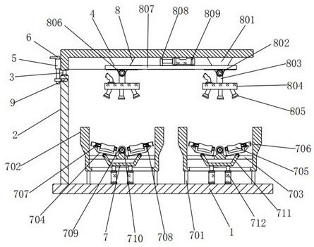
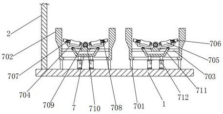
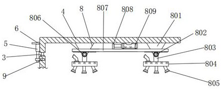
[0027] see Figure 1-6 , the present invention provides a technical solution: an automated production line for concrete pipe piles, including a base frame 1, a vertical rod 2 is fixedly connected to the left side of the top of the bottom frame 1, and a round rod 3 is connected to the top of the vertical rod 2 in rotation. 3 Make the processing frame 4 rotatable and adjustable, the top of the round rod 3 is provided with a processing frame 4, the bottom left en...


PUM


Abstract

The invention discloses an automatic production line for a concrete pipe pile. The automatic production line comprises a bottom frame, a vertical rod is fixedly connected to the left side of the top of the bottom frame, and a transmission assembly is arranged at the top of the bottom frame. According to the automatic production line for the concrete pipe pile, a grooved wheel and a belt are connected in a rotating mode, a curved frame pushes a supporting groove to enable a first round roller to abut against a pipe pile mold, so that the automatic transmission effect on the pipe pile mold can be achieved, then integrated machining is facilitated, axial rotary adjustment can be carried out on the pipe pile mold, and then the use convenience and practicability are improved; and racks are connected in a meshing mode, a flow dividing box and a bracket are correspondingly arranged, so that the flow dividing box can drive a spray head to swing in the axial direction in a reciprocating mode, then release agent spraying or water washing can be carried out on the pipe pile mold according to use requirements during transmission of the pipe pile mold, in addition, the spraying uniformity is better, omission is avoided, then the cleanliness of the pipe pile mold is improved, the demolding effect is better, and then the pipe pile quality is improved.

Description

technical field [0001] The invention relates to the technical field of an automatic production line for concrete pipe piles, in particular to an automatic production line for concrete pipe piles. Background technique [0002] Pipe piles are divided into prestressed concrete pipe piles (PC pipe piles), prestressed concrete thin-walled pipe piles (PTC pipe piles) and prestressed high-strength concrete pipe piles (PHC pipe piles) according to the concrete strength grade and wall thickness. The concrete strength of PC piles shall not be lower than C50 concrete, the strength grade of PTC pipe piles shall not be lower than C60, and the concrete strength grade of PHC piles shall not be lower than C80. PC piles and PTC piles are generally cured by atmospheric pressure steam, and it usually takes 28 days before they can be driven. For PHC piles, after demoulding, they need to be steamed in an autoclave. After 10 atmospheres of pressure and 180 degrees of autoclave curing, the shorte...

Claims


Application Information

Patent Timeline
IPC IPC(8): B28B15/00B28B17/00B28B21/00B28B7/38E02D5/30
CPCB28B15/00B28B17/00B28B17/0063B28B21/00B28B7/382B28B7/386B28B7/388E02D5/30
Inventor 不公告发明人
Owner 嘉兴市通用水泥构件有限公司
Learn More