Textile fabric dyeing equipment with cleaning and dust removing functions

A technology for dyeing equipment and textiles, applied in the field of textiles, can solve the problems of inability to synchronously clean and dedust, affect the dyeing effect, poor dyeing effect, etc., and achieve the effects of thorough cleaning process, good dyeing effect and simple structure

Inactive Publication Date: 2021-01-29
蒋自英
View PDF0 Cites 2 Cited by
  • Summary
  • Abstract
  • Description
  • Claims
  • Application Information

AI Technical Summary

Problems solved by technology

[0003] There is still a period of time before textiles are dyed after weaving. After a period of time, the surface of the textiles will be dusty, which will affect the dyeing effect. Therefore, it is necessary to clean and dust the textiles that are about to be dyed.
However, the existing dyeing devices often cannot perform cleaning and dust removal operations synchronously during dyeing, and the dyeing effect is not good.

Method used


Image

  • Textile fabric dyeing equipment with cleaning and dust removing functions
  • Textile fabric dyeing equipment with cleaning and dust removing functions
  • Textile fabric dyeing equipment with cleaning and dust removing functions

Examples


Embodiment 1

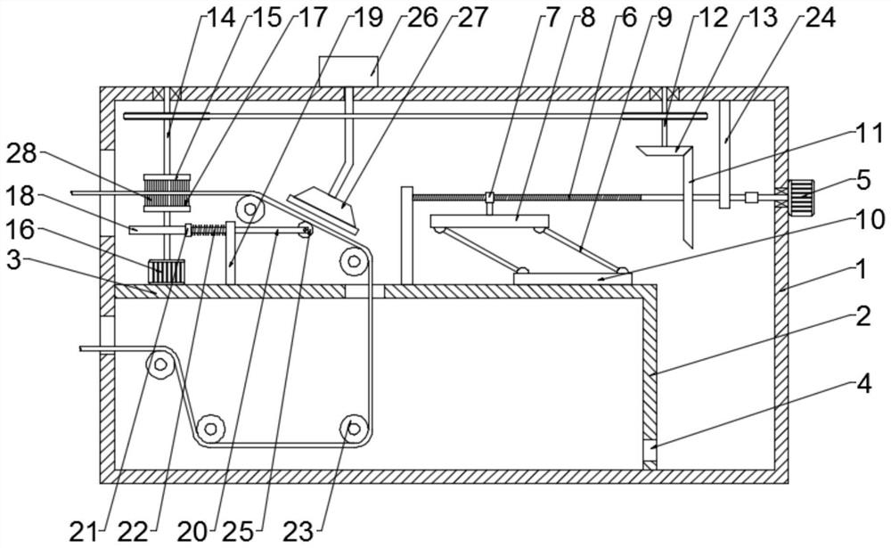
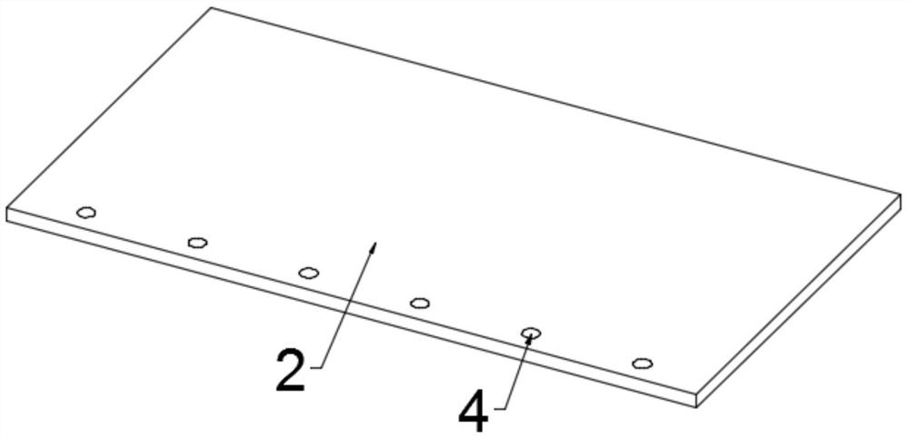
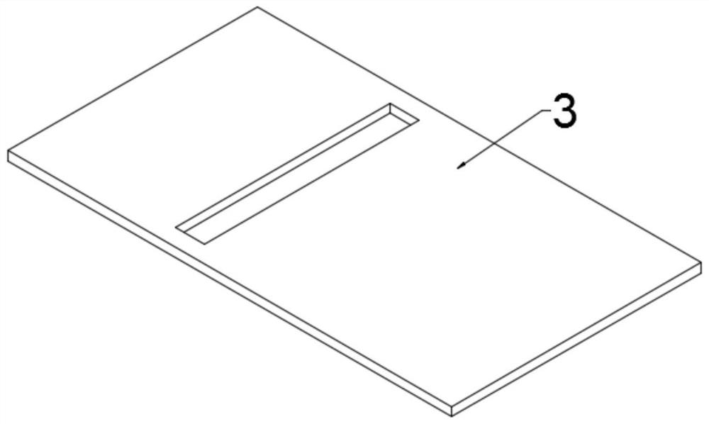
[0021] Example 1: Please refer to Figure 1-3 , a kind of textile dyeing equipment with cleaning and dust removal function, comprising an equipment box 1, a vertical partition 2 is fixedly connected to the right side of the equipment box 1, a horizontal partition 3 is fixedly connected to the top of the vertical partition 2, and the horizontal partition 3 A through hole 4 is opened at the bottom, a first motor 5 is fixedly connected to the right side of the equipment box 1, and a drive screw 6 is connected to the output end of the first motor 5 through the equipment box 1;

[0022] During use, the textile is moved through the inner side of the device through the guidance of the guide roller 23, the first motor 5 is turned on, and the rotation of the first motor 5 drives the driving screw 6 to rotate;

[0023] The outside of the drive screw 6 is threadedly connected with a drive sleeve 7, the lower part of the drive sleeve 7 is fixedly connected with an upper slide plate 8, and...

Embodiment 2

[0034] Example 2: Please refer to Figure 1-3 , a kind of textile dyeing equipment with cleaning and dust removal function, comprising an equipment box 1, a vertical partition 2 is fixedly connected to the right side of the equipment box 1, a horizontal partition 3 is fixedly connected to the top of the vertical partition 2, and the horizontal partition 3 A through hole 4 is opened at the bottom, a first motor 5 is fixedly connected to the right side of the equipment box 1, and a drive screw 6 is connected to the output end of the first motor 5 through the equipment box 1;

[0035] During use, the textile is moved through the inner side of the device through the guidance of the guide roller 23, the first motor 5 is turned on, and the rotation of the first motor 5 drives the driving screw 6 to rotate;

[0036] The outside of the drive screw 6 is threadedly connected with a drive sleeve 7, the lower part of the drive sleeve 7 is fixedly connected with an upper slide plate 8, and...


PUM


Abstract

The invention discloses textile fabric dyeing equipment with cleaning and dust removing functions, and relates to the field of textiles. The equipment comprises an equipment box; a vertical partitionplate is fixedly connected to the right side of the equipment box; a horizontal partition plate is fixedly connected to the top of the vertical partition plate; a through hole is formed in the bottomof the horizontal partition plate; a first motor is fixedly connected to the right side of the equipment box; the output end of the first motor penetrates through the equipment box and is connected with a driving screw; the outer side of the driving screw is in threaded connection with a transmission sleeve; and an upper sliding plate is fixedly connected to the lower portion of the transmission sleeve. During use, the first motor and a second motor are used for driving, the first motor drives an upper cleaning disc to rotate, and the second motor drives a lower cleaning disc to rotate so as to rotationally clean the upper surface and the lower surface of a textile fabric; in addition, the second motor can drive the textile fabric to move, so that the dust collection process is more thorough; and the first motor drives a lower sliding plate to move up and down on the right side of the vertical partition plate while rotating, so that dyeing liquid in the equipment box is promoted to flow, dyeing can be more sufficiently carried out, and the dyeing effect is good.

Description

technical field [0001] The invention relates to the field of textiles, in particular to a textile dyeing device with cleaning and dust removal functions. Background technique [0002] Textiles are a product made of textile fibers through processing and weaving. They are divided into two categories: woven fabrics and knitted fabrics. China is one of the earliest countries in the world to produce textiles. The main producing areas are Puyuan in Zhejiang and Qinghe in Hebei. [0003] After the textiles are woven, there is still a period of time before they are dyed. After a period of time, the surface of the textiles will be dusty, which will affect the dyeing effect. Therefore, it is necessary to clean and remove the dust of the textiles to be dyed. However, the existing dyeing devices often cannot perform cleaning and dust removal operations synchronously during dyeing, and the dyeing effect is not good. For this reason, those skilled in the art have proposed a textile dyein...

Claims


Application Information

Patent Timeline
IPC IPC(8): D06B3/10D06B23/20D06G1/00
CPCD06B3/10D06B23/20D06G1/00
Inventor 蒋自英
Owner 蒋自英
Why Eureka
Try Eureka