Transition section structure for underground tunnel access place and viaduct bridge connection and construction method

A technology for underground tunnels and transition sections, which is applied in the field of open-cut tunnels, which can solve problems such as large project investment, affecting the safe operation of the line, and difficult coordination of land acquisition, so as to reduce the number of projects, reduce the connection of professional interfaces, and improve structural rigidity Effect

Pending Publication Date: 2021-01-29
CHINA RAILWAY SIYUAN SURVEY & DESIGN GRP
View PDF0 Cites 2 Cited by
  • Summary
  • Abstract
  • Description
  • Claims
  • Application Information

AI Technical Summary

Problems solved by technology

[0004] 2) The permanent land occupation width of the subgrade slope structure is wider than that of bridges and tunnels; it is difficult to coordinate land acquisition and the project investment is large
[0005] 3) The design water level is higher than the ground area, there is a risk of ground and subgrade water flowing into the tunnel and submerging the tunnel, which affects the safe operation of the line

Method used


Image

  • Transition section structure for underground tunnel access place and viaduct bridge connection and construction method
  • Transition section structure for underground tunnel access place and viaduct bridge connection and construction method
  • Transition section structure for underground tunnel access place and viaduct bridge connection and construction method

Examples


Embodiment 1

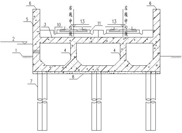
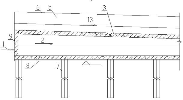
[0039]Such asfigure 1 withfigure 2 The embodiment of the present invention provides a transition section structure connecting an underground tunnel access point and a viaduct, including a transition section structure extending longitudinally along the line, the transition section structure including a bottom plate, and side plates are respectively provided on both sides of the bottom plate. The wall 5 forms a U-shaped groove, and a lane plate 3 for supporting the track bed structure 11 is provided in the transition section structure.

[0040]Further, the lane slab 3 is arranged on a slope along the longitudinal direction of the line, and is used to transition the height difference between the underground tunnel and the viaduct or high roadbed.

[0041]Further, one end of the transition section structure is connected to the underground tunnel, and the other end is connected to the viaduct, or it can be connected to the high roadbed; one end of the lane slab in the transition section struct...

Embodiment 2

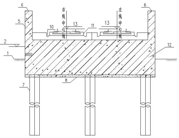
[0053]Seeimage 3 withFigure 4This embodiment provides a transition section structure connecting the access area of ​​an underground tunnel with a viaduct. The difference from the first embodiment is that the transition section structure is located between the bottom plate and the driveway slab and filled with plain concrete 12 instead of the bearing wall / For load-bearing columns, there is no need for retaining walls at the ends at this time.

[0054]The other technical features of this embodiment are the same as the first embodiment.

Embodiment 3

[0056]In view of the differential settlement of the transition section from the existing underground tunnel to the elevated tunnel and the insufficiency of the design water level 2 control, seefigure 1 withfigure 2 The embodiment of the present invention proposes a construction method of a transition section structure connecting an underground tunnel access area and a viaduct, including the following steps:

[0057]1. Use the open excavation method to clear the ground,figure 1 withfigure 2 Among them, 1 is the ground line, combined with the design water level 2, and the ground conditions are used to construct the composite foundation or bearing pile / uplift pile 7;

[0058]2. Laying cushions and constructing the structural bottom plate, which is effectively connected with the bearing pile / uplift pile 7 steel bars;

[0059]3. Determine the track elevation 13 of the lane slab 3 according to the longitudinal slope of the line, construct the structural side walls 5 on both sides of the bottom pla...


PUM


Abstract

The invention relates to a transition section structure for underground tunnel access place and viaduct bridge connection and a construction method. The transition section structure comprises a transition section structure body extending longitudinally along a line, wherein the transition section structure body comprises a bottom plate and side walls located at two sides of the bottom plate; a lane plate used for supporting ballast bed structures is arranged in the transition section structure body and located above the bottom plate; the lane plate is arranged in a slope mode in the longitudinal direction of the line; and a lane plate structure is arranged in the transition section structure body to solve the height difference problem that the rail surface is higher than the ground, and the height of boundary rail surfaces between tunnels and roadbeds and between tunnels and bridges is enlarged and higher than the designed water level. Open-cut U-shaped grooves are directly adopted tobe provided with the lane plate structure to be connected with viaduct bridges, short roadbeds are omitted, composite foundations, bearing piles and other measures are arranged on the bottom plate ofU-shaped groove structures according to different geological conditions, the structural rigidity is improved, the problem of differential settlement caused by different structural rigidities is solved, and land acquisition of roadbed sections is reduced.

Description

Technical field[0001]The invention belongs to the technical field of open-cut tunnels, and specifically relates to a transition section structure and a construction method for connecting an underground tunnel access area and a viaduct in soft soil layers and areas where the design water level is higher than the ground.Background technique[0002]With the rapid development of my country's economy and society, more and more railways use underground lines in urban areas. The existing intercity, urban, and rail transit urban underground lines to suburban elevated lines mostly adopt short-circuit foundation transitional viaduct schemes. The design technology of this scheme is mature and widely used. Through the transition of short-circuit base structure, it can make the transition between underground tunnel access tunnel and overhead line bridge structure smoothly. However, in soft soil layers and areas where the designed water level is higher than the ground, the program still has the fol...

Claims


Application Information

Patent Timeline
Patent Type & Authority Applications(China)
IPC IPC(8): E02D29/045E01B1/00E02D5/22E02D29/02E01D21/00E01F8/00H02G9/08
CPCE01B1/00E01D21/00E01F8/00E02D5/22E02D29/02E02D29/045H02G9/08
Inventor 许洪伟张迪彭莉超陈登科李越
Owner CHINA RAILWAY SIYUAN SURVEY & DESIGN GRP
Why Eureka
Try Eureka