
Continuous drilling and cyclic pouring integrated piling tool

A tool and circulation device technology, applied in the direction of rotary drilling, percussion drilling, drilling pipe, etc., can solve the problems of multi-time, mismatch and lag, failure to comprehensively consider, etc., to achieve simple operation, reliable circulation, The effect of simple structure

Active Publication Date: 2021-01-29
SOUTHWEST PETROLEUM UNIV +1
View PDF7 Cites 1 Cited by
  • Summary
  • Abstract
  • Description
  • Claims
  • Application Information

AI Technical Summary

Problems solved by technology

[0002] In the piling process of building infrastructure, due to the complexity and unpredictability of geological structures in different regions, the performance requirements of piling tools may not match and lag behind the conditions in the pile well, which will lead to drilling, cuttings removal, and pouring efficiency. Low
The performance of such piling tools cannot meet the needs of efficient piling, because the design of the drill bit structure of the piling machine has not comprehensively considered geological factors such as sandy soil, clayey soil, silty soil, and rock interlayers during the drilling process; The three processes of stopping drilling, lifting the drill barrel and dumping cuttings are carried out in sequence. When operating a deep pile well, the process of lifting the drill barrel and dumping cuttings takes more time, and the drilling and cuttings removal processes are performed alternately. Chip removal circulation mode; the pouring process needs to lift the piling equipment after piling is completed, and replace other special pouring tools in order to realize continuous pouring of concrete
Causes the "intermittent" phenomenon of drilling construction, chip removal circulation, and pouring operations in the hard layer
There is "intermittent" After drilling, it takes more time, financial resources, material resources and manpower

Method used


Image

  • Continuous drilling and cyclic pouring integrated piling tool
  • Continuous drilling and cyclic pouring integrated piling tool
  • Continuous drilling and cyclic pouring integrated piling tool

Examples


Embodiment approach

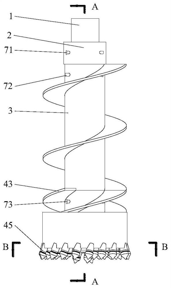
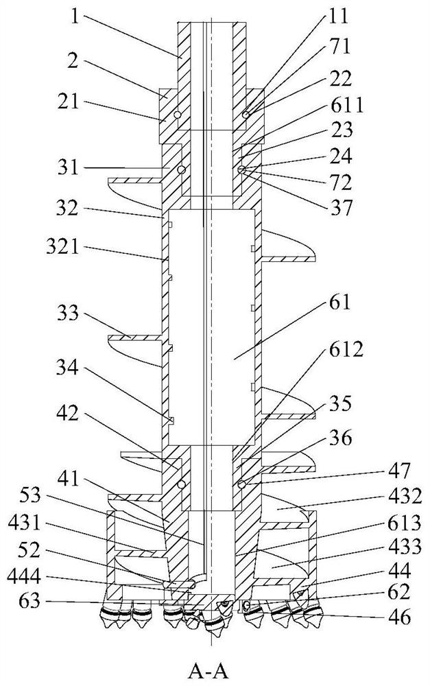
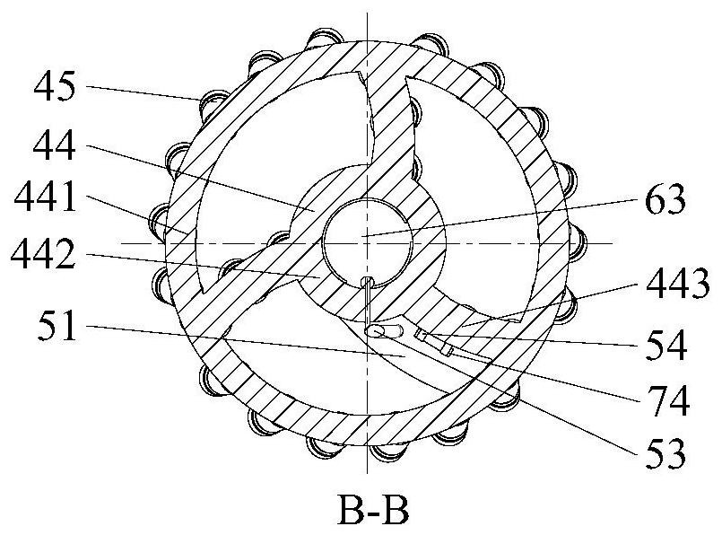
[0034] In the above-mentioned one embodiment, efficient drilling, synchronous chip removal, and continuous pouring are realized by using the power connector 2, the circulation device 3, the drill parts, the cleaning mechanism and the pouring mechanism. In this embodiment, the torque and bit pressure are transmitted through the power connector 2 and the circulation device 3, and the drill bit part 4 is driven to screw in, and the synchronization of chip removal is realized through the circulation device 3; when drilling into the geological formation that meets the requirements, The external control pushes the bottom cleaning cutter head 51 out by stretching the control member 52 to realize the removal of debris at the bottom of the well; after the bottom cleaning operation is completed, there is no need to replace the pouring equipment, and efficient continuous pouring operations are realized. When drilling normally, under the action of axial pressure and circumferential force, ...


PUM


Abstract

The invention belongs to the field of constructional engineering and mechanical engineering, and particularly relates to a continuous drilling and cyclic pouring integrated piling tool. According to the technical scheme, the continuous drilling and cyclic pouring integrated piling tool comprises a power connecting piece, a circulating device, a drill bit component, a bottom cleaning mechanism anda pouring mechanism, wherein the circulating device comprises a circulating drilling barrel and a spiral piece, both ends of the circulating drilling barrel are respectively connected with the power connecting piece and the drill bit component or the circulating drilling barrel, and the spiral piece is connected with the circulating drilling barrel; the drill bit component comprises a drill bit base, a drill bit seat and a drill bit, the drill bit seat is connected with the drill bit base, and the drill bit is connected with the drill bit seat; the bottom cleaning mechanism comprises a connecting rod and bottom cleaning blades; and the pouring mechanism comprises a pouring channel and a control piece. The invention provides a novel continuous drilling and cyclic pouring integrated piling tool, and the piling drilling and cyclic chip removal and continuous pouring efficiency is improved.

Description

technical field [0001] The invention belongs to the fields of construction engineering and mechanical engineering, and in particular relates to an integrated piling tool for continuous drilling and cyclic pouring. Background technique [0002] In the piling process of building infrastructure, due to the complexity and unpredictability of geological structures in different regions, the performance requirements of piling tools may not match and lag behind the conditions in the pile well, which will lead to drilling, cuttings removal, and pouring efficiency. Low. The performance of such piling tools cannot meet the needs of efficient piling, because the design of the drill bit structure of the piling machine has not comprehensively considered geological factors such as sandy soil, clayey soil, silty soil, and rock interlayers during the drilling process; The three processes of stopping drilling, lifting the drill barrel and dumping cuttings are carried out in sequence. When op...

Claims


Application Information

Patent Timeline
Patent Type & Authority Applications(China)
IPC IPC(8): E21B10/42E21B10/43E21B10/44E21B3/00E21B21/00E02D5/34
CPCE21B10/42E21B10/43E21B10/44E21B3/00E21B21/00E02D5/34E02D5/46E21B17/22E21B10/60
Inventor 田家林唐磊李岩邢春雨
Owner SOUTHWEST PETROLEUM UNIV
Learn More