Tail nozzle temperature field visualization device based on binocular vision and identification method thereof

A technology of binocular vision and tail nozzle, which is applied in measurement devices, temperature distribution maps, radiation pyrometry, etc. The effect of a small amount of calculation

Active Publication Date: 2021-01-29
AECC SICHUAN GAS TURBINE RES INST
View PDF24 Cites 0 Cited by
  • Summary
  • Abstract
  • Description
  • Claims
  • Application Information

AI Technical Summary

Problems solved by technology

The grayscale-based segmentation method can only deal with graphics with clear layers and clear boundaries. In the engine room test, the boundary is blurred and the layers are complex. A large amount of data is used to train the recognition algorithm, which requires a large amount of calculation, and is also not suitable for engine exhaust image segmentation

Method used


Image

  • Tail nozzle temperature field visualization device based on binocular vision and identification method thereof
  • Tail nozzle temperature field visualization device based on binocular vision and identification method thereof
  • Tail nozzle temperature field visualization device based on binocular vision and identification method thereof

Examples


Embodiment Construction

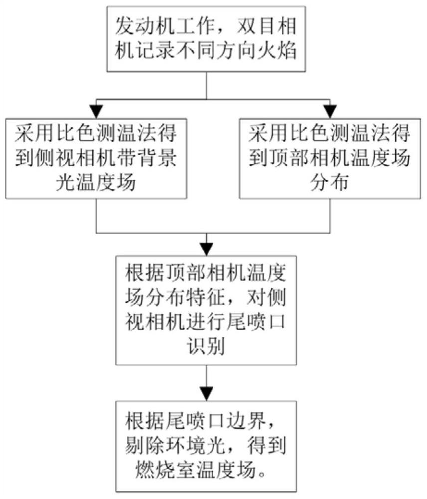
[0032] The invention proposes a method for measuring the temperature field of an engine combustion chamber with simple structure, clear principle and accurate measurement. It overcomes the problem of limited temperature measurement points and great influence on the flow field, and overcomes the problem that the existing image segmentation technology cannot accurately segment the engine exhaust nozzle. The binocular vision solution is used to measure the temperature field of the engine exhaust flame and the image recognition of the exhaust nozzle, so as to achieve the purpose of real-time, efficient and accurate measurement of the temperature field of the engine combustion chamber.

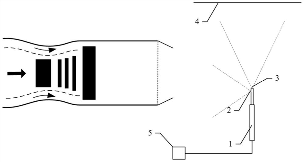
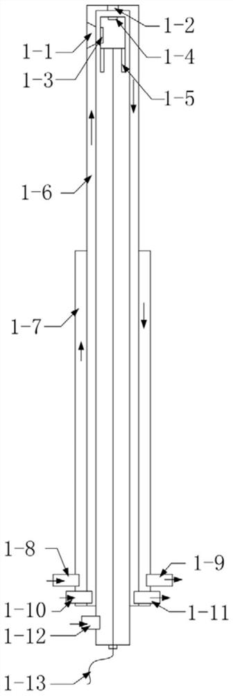
[0033] Provide a binocular CCD camera temperature field measurement cooling probe and temperature field post-processing and tail nozzle identification program, such as figure 1 As shown, it includes a cooling probe 1 , a side viewing angle 2 , a top viewing angle 3 , a top black background plate 4 ...


PUM


Abstract

The invention belongs to the field of aero-engine tests, and relates to a tail nozzle temperature field visualization device based on binocular vision and an identification method thereof. The tail nozzle temperature field visualization device comprises a cooling probe, a top black background plate, and a processor storing temperature field measurement and tail nozzle recognition post-processing programs, wherein the cooling probe is located at the lower position of the central axis of the engine tail nozzle; a binocular camera is arranged in the cooling probe; the binocular camera has a top view angle along the axial direction of the cooling probe and a side view angle along the radial direction of the cooling probe; the top black background plate is located within the top view angle; theengine tail nozzle is positioned within the side view angle; and the binocular camera of the cooling probe sends a shot image to the processor, so that the image is processed according to a processing program stored in the binocular camera, and a temperature field of the combustion chamber is obtained.

Description

technical field [0001] The invention belongs to the field of aero-engine testing, and relates to a binocular vision-based visualization device for the temperature field of an exhaust nozzle and an identification method thereof. Background technique [0002] With the increase of engine thrust, the working environment of the combustion chamber is getting worse and higher, and the working temperature is getting higher and higher. How to monitor the temperature field of the combustion chamber in real time, efficiently and accurately with little influence on the flow field of the combustion chamber is very important for the study of engine combustion , to improve engine performance and to ensure test safety is very important. [0003] The traditional thermocouple method can only measure the temperature of a limited number of points. When there are many measuring points, the galvanic couple rake will greatly interfere with the flow field. Machine vision temperature field measurem...

Claims


Application Information

Patent Timeline
Patent Type & Authority Applications(China)
IPC IPC(8): G01J5/00G01J5/08G01J5/10G06T7/00G06T7/194
CPCG01J5/0018G01J5/10G01J5/0875G06T7/0002G06T7/194G01J2005/0077G06T2207/10024G01J5/485
Inventor 陈鹏飞吴锋杨华何培垒尹骥张建武
Owner AECC SICHUAN GAS TURBINE RES INST
Why Eureka
Try Eureka