High-energy micro-focus X-ray production equipment

A production equipment, X-ray technology, applied in the directions of X-ray equipment, X-ray tubes, X-ray tubes with huge current, etc., can solve the problems of large focal size of the ray source, unfavorable detection of small details, and low imaging resolution, etc. Overcome the effects of small focus size, reduced focus size, and high ray energy

Pending Publication Date: 2021-01-29
INST OF APPLIED ELECTRONICS CHINA ACAD OF ENG PHYSICS
View PDF0 Cites 3 Cited by
  • Summary
  • Abstract
  • Description
  • Claims
  • Application Information

AI Technical Summary

Problems solved by technology

The traditional high-energy accelerator ray source has a large focus size (about 2.0mm) and low imaging resolution, which is not conducive to the detection of tiny details

Method used


Image

  • High-energy micro-focus X-ray production equipment
  • High-energy micro-focus X-ray production equipment
  • High-energy micro-focus X-ray production equipment

Examples


Embodiment Construction

[0030] In order to make those skilled in the art better understand the technical solution of the present invention, the technical solution of the present invention is clearly and completely described below in conjunction with the accompanying drawings of the present invention. Based on the embodiments in this application, those of ordinary skill in the art will Other similar embodiments obtained without creative work shall all fall within the scope of protection of this application. In addition, the directional words mentioned in the following embodiments, such as "upper", "lower", "left", "right", etc., are only referring to the directions of the drawings, therefore, the directional words used are for illustration rather than limitation invent.

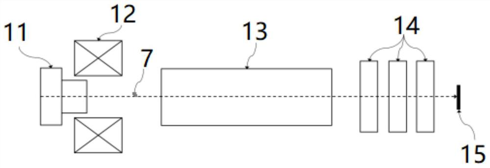
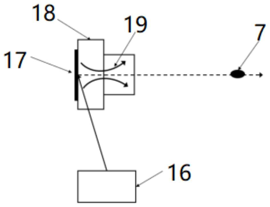
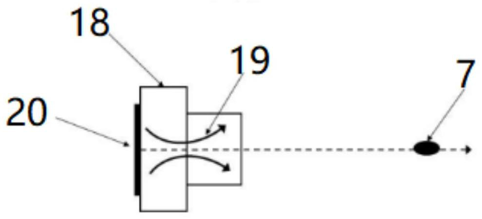
[0031] Such as Figure 1-10 As shown, a high-energy micro-focus X-ray production equipment includes an electron source 11 assembly for generating a high-energy electron beam and a rotating target device 15 for being bombarded by an ...


PUM


Abstract

The invention discloses high-energy micro-focus X-ray production equipment, which comprises an electron source assembly used for generating high-energy electron beams and rotating target equipment used for being bombarded by the electron beams to generate high-energy X-rays, and the high-energy focused electron beams generated by the electron source assembly are bombarded to the rotating target equipment to generate high-energy micro-focus X-rays. According to the invention, a specific electron source and a linear accelerator are matched to provide the electron beam with long macro pulse and high average flow intensity, and the transverse size of the electron beam with long macro pulse and high average flow intensity is focused to a relatively small size at a targeting position through thefocusing of a solenoid and a strong focusing quadrupole lens group; and a beam spot measuring assembly is used for precisely measuring and controlling the transverse size of the electron beam, the size of the beam spot is controlled to 0.1mm or below, and the purpose of high-energy micro-focus X-ray output is achieved.

Description

technical field [0001] The invention belongs to the field of radiation devices, in particular to a high-energy micro-focus X-ray production equipment. Background technique [0002] Industrial CT (Industrial Computed Tomography), as the best non-destructive testing method, can visually display the internal structure information of objects, and can locate defects and measure spatial dimensions. It is widely used in aerospace, aviation, nuclear power, metallurgy, machinery, electronics, construction Non-destructive testing, non-destructive evaluation and reverse engineering in petrochemical and other fields. [0003] X-ray sources are the core components of industrial CT imaging, mainly low-energy micro-focus ray sources, conventional X-ray tube ray sources and traditional high-energy accelerator ray sources. The electron beam is used to accelerate the target in an electric field, and the bremsstrahlung is converted into X-rays. Low-energy micro-focus ray source (voltage <...

Claims


Application Information

Patent Timeline
Patent Type & Authority Applications(China)
IPC IPC(8): H05G2/00G01N23/046G01B15/00
CPCG01B15/00G01N23/046H05G2/00H05G2/008
Inventor 李鹏王建新周征胡栋材肖德鑫吴岱黎明杨兴繁王远王孝忠赵剑衡陈门雪鲁燕华王汉斌刘宇单李军沈旭明和天慧徐勇周奎劳成龙罗星白燕闫陇刚邓德荣陈立均刘婕张德敏潘清柏伟陈亚男邓仕钰李文君宋志大张成鑫刘清华李敬李寿涛李世根程云蒲晓媛涂国锋蔡哲陈云斌力涛石正军罗为刘春林张小丽张冬余虹丁玉寿李雷
Owner INST OF APPLIED ELECTRONICS CHINA ACAD OF ENG PHYSICS
Why Eureka
Try Eureka