Eureka AIR delivers breakthrough ideas for toughest innovation challenges, trusted by R&D personnel around the world.

Lubricating ring and clutch module comprising such a lubricating ring

A technology for lubricating rings and clutches, which is applied in clutches, friction clutches, fluid-driven clutches, etc., and can solve the problems of clutch module assembly difficulties, technical and operational difficulties, etc.

Active Publication Date: 2021-02-02
VALEO EMBRAYAGES SAS
View PDF16 Cites 0 Cited by
  • Summary
  • Abstract
  • Description
  • Claims
  • Application Information

AI Technical Summary

Problems solved by technology

Lubricating rings are generally located axially between the bearings that absorb the radial load of the clutch module and the torque transmission hub of said clutch module, which causes greater difficulties when assembling the clutch module
A known issue is related to the technical and operational difficulties involved in installing the lube ring on the clutch module

Method used


Image

  • Lubricating ring and clutch module comprising such a lubricating ring
  • Lubricating ring and clutch module comprising such a lubricating ring
  • Lubricating ring and clutch module comprising such a lubricating ring

Examples


Embodiment Construction

[0055] In the following description and claims, for ease of understanding, the following terms will be used without limitation:

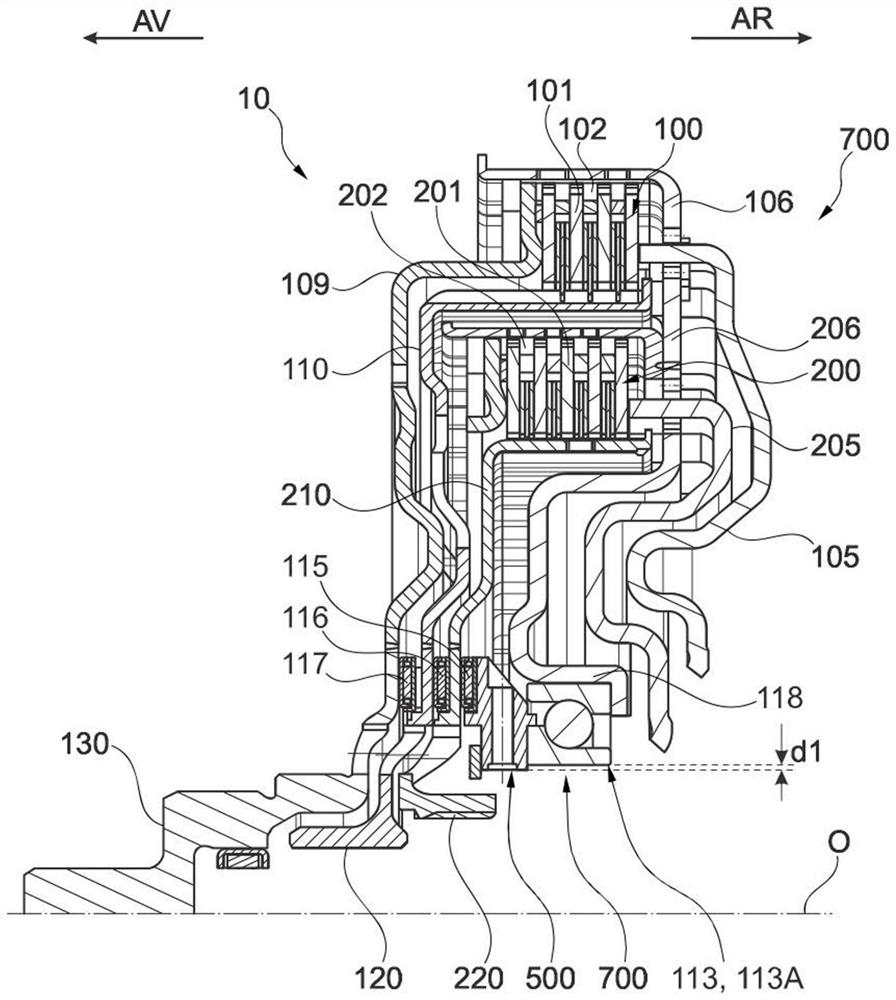
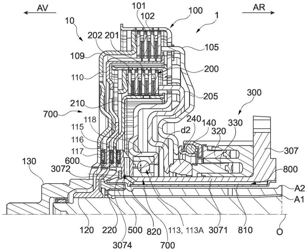
[0056] - "front" or "rear" in a direction defined relative to the axial orientation determined by the axis of rotation O of the clutch module or assembly, "rear" meaning the part located on the right in the figure, for example on the side of the gearbox, and "front" means the left part of the figure, such as the side of the internal combustion engine; and

[0057] - "inner / inner" or "outer / external" with respect to the axis of rotation O and in a radial orientation orthogonal to the axial orientation, "inner" meaning the part near the axis of rotation O and "outer" meaning the The part away from the axis of rotation O.

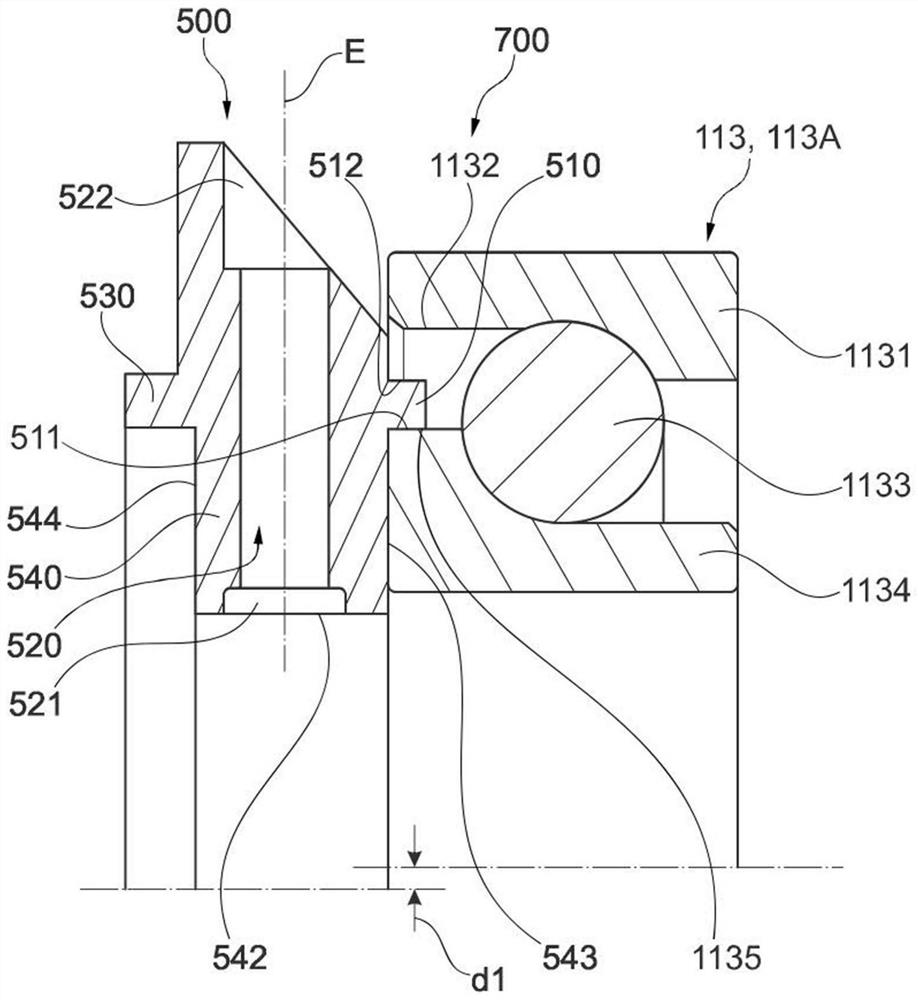
[0058] figure 1 An embodiment of an assembly 700 according to the second aspect of the invention is shown, comprising a lubricating ring 500 according to the first aspect of the invention and a release bearing 113A.

[0059] The ...


PUM


Abstract

The invention concerns a lubricating ring (500) that assists in the axial immobilisation of the clutch module (1), said lubricating ring (500) being located against the support bearing (113) and forming an assembly (700) with same. The lubricating ring (500) comprises a pre-centring bearing surface (510) that allows a temporary assembly configuration to be produced with the support bearing (113),when the assembly (700) is pre-assembled before being integrated into the clutch module (1). In this temporary assembly configuration, the lubricating ring (500) bears radially against one of the annular rings (1131, 1134) of the support bearing, eccentrically with respect to the support bearing (113). When the assembly (700) is mounted on the clutch module, the lubricating ring (500) is re-centred with respect to the support bearing (113), such that the inner contour (542) of said lubricating ring (500) is coaxial with the inner face of the inner annular ring (1134) of the support bearing (113).

Description

technical field [0001] The technical background of the invention is the circulation of hydraulic fluid within a motor vehicle clutch module. More specifically, the present invention relates to lubricating rings, assemblies including such lubricating rings associated with release bearings, and clutch modules including such assemblies. Background technique [0002] During its operation, the known wet clutch mechanism generates friction to allow torque to be transmitted between an input shaft rotationally driven by the crankshaft of the engine on the one hand and at least one output shaft rotationally coupled to the gearbox on the other hand. In particular, at each clutch the frictional coupling is achieved by means of a plurality of frictional elements capable of engaging or disengaging the rotational coupling of the input shaft relative to a respective one of the output shafts. [0003] In a known manner, the friction elements of each clutch heat up during the transition pha...

Claims


Application Information

Patent Timeline
IPC IPC(8): F16D13/74F16D13/52F16D21/06
CPCF16D2021/0661F16D25/123F16D25/10F16D25/082
Inventor A.多尔F.蒂博G.武亚罗奎奥克斯
Owner VALEO EMBRAYAGES SAS
Why Eureka
Eureka Blog
Learn More