Transformer copper strip edge burr treatment device and method

A processing device and a technology for a transformer are applied in the field of burr removal equipment on the edge of a copper strip of a transformer, which can solve the problems of complicated operation and difficult adjustment, and achieve the effect of excellent processing effect.

Pending Publication Date: 2021-02-05
TONGLING NON FERROUS METAL GROUP CORP
View PDF5 Cites 3 Cited by
  • Summary
  • Abstract
  • Description
  • Claims
  • Application Information

AI Technical Summary

Problems solved by technology

The operation is complicated, the selection of tools and the adjustment of the cutting angle are difficult to complete, and it is necessary to continuously test and verify the problem

Method used


Image

  • Transformer copper strip edge burr treatment device and method
  • Transformer copper strip edge burr treatment device and method
  • Transformer copper strip edge burr treatment device and method

Examples


Embodiment 1

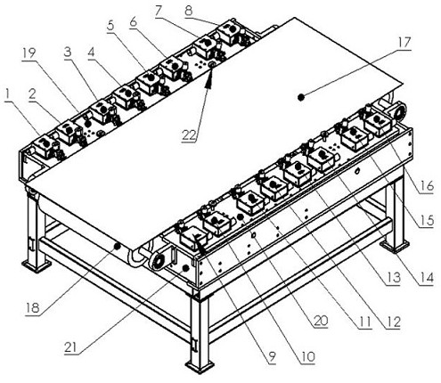
[0035] Example 1, see figure 1, the present invention provides a technical solution: a transformer copper strip edge burr treatment device, including a frame 21, the front and rear ends of the frame 21 are provided with transformer copper strip stabilizing rollers 18, two of the transformer copper strip stabilizing rollers 18 A transformer steel strip 17 is placed between the tops of the frame 21, movable left cutter head mounting plate 19 and right cutter head mounting plate 20 are arranged on both sides of the frame 21, and cutter head mounting plates 19 are arranged on the left side cutter head mounting plate in turn. 45 degrees to the upper left of the assembly 1, 60 degrees to the upper left of the cutter head assembly 2, 30 degrees to the upper left of the cutter head assembly 3, upper left arc of the cutter head assembly 4, 45 degrees to the lower left of the cutter head assembly 5, 60 degrees to the lower left of the cutter head assembly 6. The cutter head assembly is ...

Embodiment 2

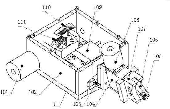
[0036] Example 2, see Figure 2-7 , Cutter head assembly left upper 45 degrees 1, Cutter head assembly left upper 60 degrees 2, Cutter head assembly left upper 30 degrees 3, Cutter head assembly left upper arc 4, Cutter head assembly lower left 45 degrees 5, Cutter head assembly Lower left 60 degrees 6. Cutter head assembly lower left 30 degrees 7. Cutter head assembly lower left arc 8. Cutter head assembly upper right 45 degrees 9. Cutter head assembly upper right 60 degrees 10. Cutter head assembly upper right 30 degrees 11. The upper right arc of the cutter head assembly 12, the lower right of the cutter head assembly 45 degrees 13, the lower right 60 degrees of the cutter head assembly 14, the lower right 30 degrees of the cutter head assembly 15 and the lower right arc 16 of the cutter head assembly There is knife box 102, and a side of knife box 102 is equipped with cutter head rotation adjustment handle 101, and the inner bottom surface of knife box 102 is equipped with...


PUM


Abstract

The invention discloses a transformer copper strip edge burr treatment device and method. The device comprises a rack, transformer copper strip stabilizing rolls are arranged at the front end and therear end of the rack correspondingly, and a transformer steel strip is placed between the tops of the two transformer copper strip stabilizing rolls. A movable left tool bit mounting plate and a movable right tool bit mounting plate are arranged on the two sides of the rack correspondingly. A tool bit assembly upper left 45-degree part, a tool bit assembly upper left 60-degree part, a tool bit assembly upper left 30-degree part, a tool bit assembly upper left arc part, a tool bit assembly lower left 45-degree part, a tool bit assembly lower left 60-degree part and a tool bit assembly lower left 30-degree part are sequentially mounted on the left tool bit mounting plate. According to the device provided by the invention, an excellent transformer strip edge treatment effect is obtained in use, the strip edge is smooth and free of burrs, the supply of domestic high-precision transformer strips can be realized, one specification of flat knives is adopted, an arc knife is obtained by machining an arc cutting edge on a flat knife, and the knife is used according to the thickness specification of the strip, so that the knife use cost is reduced, and operation is simplified; and the operating efficiency is improved.

Description

technical field [0001] The invention relates to the technical field of equipment for removing burrs at the edge of transformer copper strips, in particular to a device and method for processing burrs at the edge of transformer copper strips. Background technique [0002] The dry-type transformer is composed of a high-voltage winding and a low-voltage winding. The high-voltage winding is wound with narrow and thin copper strips, and the low-voltage copper strip is wound with wide and thick copper strips. The thickness of the copper strips is 0.1mm-3mm and the width is 14mm-1200mm. Because there are burrs in the cutting of the edge of the strip, which may puncture the insulation and cause breakdown or damage the transformer due to tip discharge, the height of the burr must be controlled on the edge of the strip. At present, the rolling method is used in China to press the burr, but the burr cannot be removed. The scraping method is used abroad to process the edge of the strip ...

Claims


Application Information

Patent Timeline
Patent Type & Authority Applications(China)
IPC IPC(8): B23D79/00
CPCB23D79/00
Inventor 徐斌
Owner TONGLING NON FERROUS METAL GROUP CORP
Why Eureka
Try Eureka