Supercharge Your Innovation With Domain-Expert AI Agents!

Garbage pyrolysis gasification incineration system and method

A pyrolysis gasification and garbage technology, applied in the field of waste pyrolysis gasification incineration system, can solve the problems of overcapacity, high cost of waste recycling, low processing efficiency, etc., and achieve the goal of reducing energy consumption and high harmless conversion rate Effect

Pending Publication Date: 2021-02-05
重庆秋松环保科技有限公司
View PDF11 Cites 0 Cited by
  • Summary
  • Abstract
  • Description
  • Claims
  • Application Information

AI Technical Summary

Problems solved by technology

[0002] Due to the current overcapacity, the cost of waste recycling in daily life is too high, people are unwilling to recycle, and become garbage that can be seen everywhere
Now the conventional means of garbage disposal is landfill. For landfill, each city covers an area of ​​tens of acres of garbage every day. As the land becomes less and less, landfill has become an urgent alternative. As a result, waste incineration treatment methods have emerged. Although a large amount of toxic and harmful gases will be produced in the process of waste incineration, the pollution can be significantly reduced through post-treatment tail gas.
[0003] At present, the process of waste incineration is complicated, the treatment efficiency is low, and the heat energy of high-temperature flue gas cannot be fully utilized, which makes it difficult for the exhaust gas to meet environmental protection standards.

Method used


Image

  • Garbage pyrolysis gasification incineration system and method
  • Garbage pyrolysis gasification incineration system and method
  • Garbage pyrolysis gasification incineration system and method

Examples


Embodiment Construction

[0034] Embodiments of the present invention are described in detail below, examples of which are shown in the drawings, wherein the same or similar reference numerals designate the same or similar elements or elements having the same or similar functions throughout. The embodiments described below by referring to the figures are exemplary and are intended to explain the present invention and should not be construed as limiting the present invention.

[0035] In describing the present invention, it should be understood that the terms "length", "width", "upper", "lower", "front", "rear", "left", "right", "vertical", The orientation or positional relationship indicated by "horizontal", "top", "bottom", "inner", "outer", etc. are based on the orientation or positional relationship shown in the drawings, and are only for the convenience of describing the present invention and simplifying the description, rather than Nothing indicating or implying that a referenced device or element...


PUM


Abstract

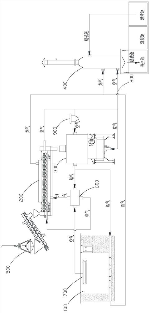
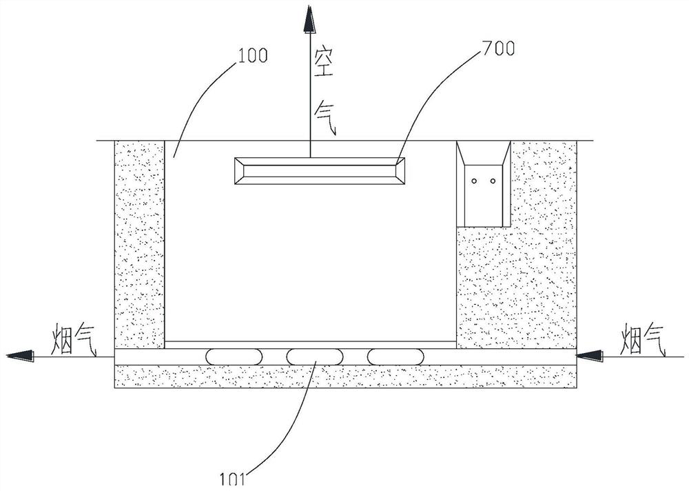
The invention relates to a garbage pyrolysis gasification incineration system and method. The garbage pyrolysis gasification incineration system comprises a garbage transfer pool, a drying device, a pyrolysis gasification device and a tail gas treatment device, a feeding port of the drying device is connected with the garbage transfer pool through a feeding device, a discharging port of the dryingdevice is connected with a feeding port of the pyrolysis gasification device, and the incineration system further comprises a heat exchange device; an exhaust port of the pyrolysis gasification device communicates with a main gas inlet of the heat exchange device, a main gas inlet of the drying device communicates with a main gas outlet of the heat exchange device, a main gas inlet of the tail gas treatment device communicates with a main gas outlet of the drying device, and an air extractor is further arranged in the garbage transfer pool; and an auxiliary gas inlet of the heat exchange device communicates with an auxiliary gas outlet of the air extractor, an auxiliary gas inlet of the drying device communicates with an auxiliary gas outlet of the heat exchange device, and an gas inlet of the pyrolysis gasification device communicates with an auxiliary gas outlet of the drying device. The garbage pyrolysis gasification incineration system has the effects that the heat of high-temperature flue gas can be recycled, and the energy consumption of the whole system is reduced.

Description

technical field [0001] The invention relates to the technical field of domestic waste treatment, in particular to a waste pyrolysis gasification incineration system and method. Background technique [0002] Due to the current overcapacity, the cost of waste recycling in daily life is too high, people are unwilling to recycle, and it has become garbage that can be seen everywhere. Now the conventional means of garbage disposal is landfill. For landfill, each city covers an area of ​​tens of acres of garbage every day. As the land becomes less and less, landfill has become an urgent alternative. As a result, waste incineration treatment methods have emerged. Although a large amount of toxic and harmful gases will be produced during the process of waste incineration, pollution can be significantly reduced through post-treatment tail gas. [0003] At present, the process of waste incineration is complicated, the treatment efficiency is low, and the heat energy of high-temperatu...

Claims


Application Information

Patent Timeline
IPC IPC(8): F23J15/06F23J15/02B01D53/50B01D53/79
CPCF23J15/06F23J15/02B01D53/504B01D53/79B01D2258/0291Y02E20/30
Inventor 陈秋松
Owner 重庆秋松环保科技有限公司
Features
  • R&D
  • Intellectual Property
  • Life Sciences
  • Materials
  • Tech Scout
  • Unparalleled Data Quality
  • Higher Quality Content
  • 60% Fewer Hallucinations
Learn More