Supercharge Your Innovation With Domain-Expert AI Agents!

Dilution refrigeration system and method

A technology of refrigeration system and refrigerator, which is applied in refrigerators, refrigeration components, refrigeration and liquefaction, etc. It can solve the problems of poor vibration isolation effect, large total specific heat capacity, and large volume, and achieve the effect of easy operation and replacement, and compact layout

Active Publication Date: 2021-02-05
格物致寒(苏州)科学仪器有限公司
View PDF7 Cites 0 Cited by
  • Summary
  • Abstract
  • Description
  • Claims
  • Application Information

AI Technical Summary

Problems solved by technology

[0006] 1. Inconvenient operation: the arrangement of existing dilution refrigerators is that the mixing chamber (that is, the coldest end) is arranged at the bottom, so samples or experimental devices that need to be cooled need to be installed at the lower part of the dilution refrigerator, which gives the sample The work of installation and removal brings a great burden; at the same time, it is not conducive to the observation of samples
[0007] 2. Slow heating and cooling speed: Due to the layout of the existing dilution refrigerator, the equipment is large in size, resulting in a large total specific heat capacity of the system, so it usually takes dozens of hours to drop from room temperature to the lowest temperature, making the experiment efficiency low
[0008] 3. Poor vibration isolation effect: The suspension design used in the layout of the existing dilution refrigerators makes it difficult to isolate the vibration of the mechanical refrigerators used for pre-cooling in the "dry" (no refrigerant) system, which affects the stability of the system. It brings adverse effects, and also makes it impossible to carry out many precise experimental measurements

Method used


Image

  • Dilution refrigeration system and method
  • Dilution refrigeration system and method
  • Dilution refrigeration system and method

Examples


Embodiment Construction

[0035] The technical solutions of the present invention will be clearly and completely described below in conjunction with the accompanying drawings. Apparently, the described embodiments are some of the embodiments of the present invention, but not all of them. Based on the embodiments of the present invention, all other embodiments obtained by persons of ordinary skill in the art without making creative efforts belong to the protection scope of the present invention.

[0036] In the description of the present invention, it should be noted that the terms "center", "upper", "lower", "left", "right", "vertical", "horizontal", "inner", "outer" etc. The indicated orientation or positional relationship is based on the orientation or positional relationship shown in the drawings, and is only for the convenience of describing the present invention and simplifying the description, rather than indicating or implying that the referred device or element must have a specific orientation, ...


PUM


Abstract

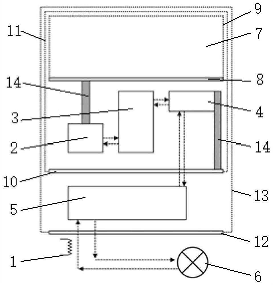
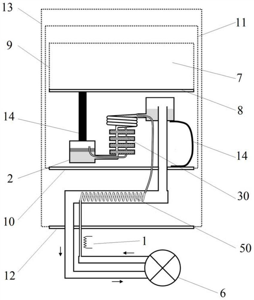
The invention relates to a dilution refrigeration system and method. The dilution refrigeration system comprises a refrigerator main body and an external refrigerator thermally coupled with the refrigerator main body; the refrigerator main body comprises a mixing chamber, a heat exchanger communicated with the mixing chamber, a distillation chamber communicated with the heat exchanger, a refrigeration / heat exchanger communicated with the distillation chamber and a circulating pump communicated with the refrigeration / heat exchanger, and the mixing chamber, the heat exchanger and the distillation chamber are distributed in the horizontal direction; and a target low-temperature area is formed above the mixing chamber, and the mixing chamber is thermally coupled with the target low-temperaturearea. According to the dilution refrigeration system, the layout is more compact, miniaturization is realized, and the dilution refrigeration system has more advantages in the aspects of heating andcooling rates and vibration isolation; and meanwhile, the target low-temperature area is arranged at the upper part of a refrigerating machine, so that a sample is easier to operate and replace, and greater convenience is brought to a user.

Description

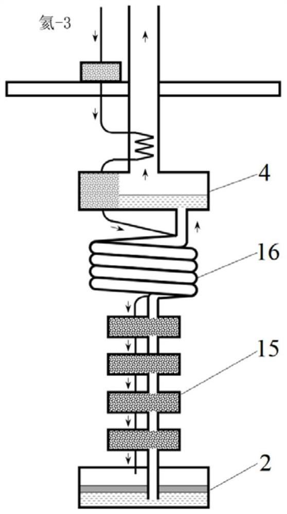
technical field [0001] The invention belongs to the technical field of refrigeration, and in particular relates to a dilution refrigeration system and method. Background technique [0002] Obtaining a stable extremely low temperature environment is a necessary basic condition for contemporary scientific research and technological progress. Usually, the extremely low temperature environment refers to the environment below 100 millikelvin (mK). Only when the temperature reaches such a low temperature, high-tech technologies such as quantum computing and far-infrared photon detection become possible. [0003] Helium-3 / helium-4 dilution refrigeration technology is currently the most mainstream technical means to obtain extremely low temperature environments. The core principle of its refrigeration is to use helium-3 as the solute and helium-4 as the solvent. The dissolution process absorbs heat to achieve the purpose of refrigeration , using the gas circuit and the pump group t...

Claims


Application Information

Patent Timeline
Patent Type & Authority Applications(China)
IPC IPC(8): F25B9/14F25B39/00
CPCF25B9/145F25B9/14F25B39/00
Inventor 郝镇齐张磊
Owner 格物致寒(苏州)科学仪器有限公司
Features
  • R&D
  • Intellectual Property
  • Life Sciences
  • Materials
  • Tech Scout
  • Unparalleled Data Quality
  • Higher Quality Content
  • 60% Fewer Hallucinations
Learn More