Wheat drying equipment with good dust removal effect
A technology for drying equipment and wheat, which is applied in drying, drying machines, lighting and heating equipment, etc., can solve the problems of low work efficiency, achieve the effect of improving practicability and dust removal effect
- Summary
- Abstract
- Description
- Claims
- Application Information
AI Technical Summary
Problems solved by technology
Method used
Image

Examples
Embodiment Construction
[0027] The present invention is described in further detail now in conjunction with accompanying drawing. These drawings are all simplified schematic diagrams, which only illustrate the basic structure of the present invention in a schematic manner, so they only show the configurations related to the present invention.
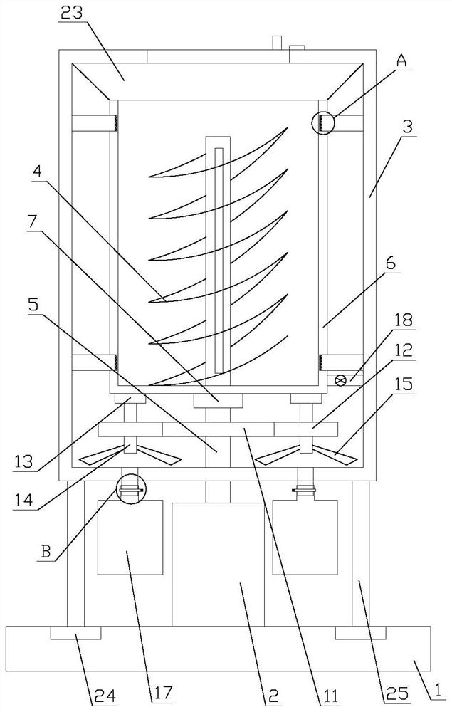
[0028] Such as Figure 1-4 As shown, a wheat drying equipment with good dust removal effect includes a base 1, a drive mechanism and a dust removal mechanism, the base 1 is arranged horizontally, and the drive mechanism and the dust removal mechanism are both arranged on the base 1;
[0029] The driving mechanism includes a stirring assembly and a rotating assembly, the rotating assembly includes a motor 2 and a rotating drum 3, the rotating drum 3 is vertically arranged above the base 1, and the motor 2 is arranged vertically upward on the base 1 , the motor 2 is located between the rotating drum 3 and the base 1, and the rotating drum 3 is installed on the ...
PUM
 Abstract
Description
Claims
Application Information
PatSnap Eureka turns technology decisions into work you can execute. Powered by our Innovation Knowledge Graph, it runs expert workflows across engineering, life sciences, materials and intellectual property. Get your review-ready output in minutes.


