Machining method of thin-wall complex cavity
A processing method and cavity technology, which are applied in the field of workpiece processing to achieve the effects of easy quality control, meeting size and precision requirements, and smooth and compact joints.
- Summary
- Abstract
- Description
- Claims
- Application Information
AI Technical Summary
Problems solved by technology
Method used
Image
Examples
Embodiment 1
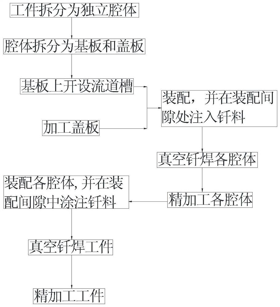
[0037] a kind of like figure 2 The processing method of the thin-walled complex cavity shown, such as figure 1 shown, including the following steps:
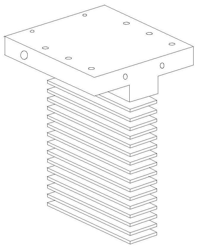
[0038] S1. If figure 2 As shown, the workpiece is split into multiple layers according to the internal flow channel structure, so that each layer becomes an independent cavity;
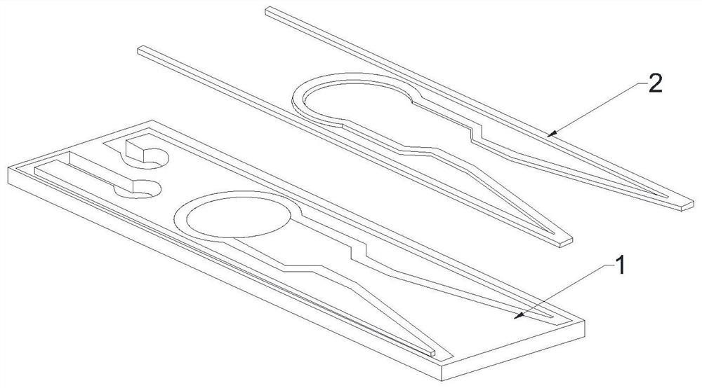
[0039] S2. If image 3 As shown, each cavity is divided into a base plate and a cover plate, a runner groove is opened on the base plate, and a cover plate matching the runner groove is processed; Figure 4 As shown, the joint form of the runner groove and the cover plate is set as a lap joint. The bottom of the runner groove is opened as a square runner, and the top is opened as a square overlap groove with a size larger than the square runner. The size of the cover plate is the same as that of the square overlap. The grooves are matched; and chamfers are processed at the top corners of the cover;
[0040] The runner groove and the cover plate o...
Embodiment 2
[0060] On the basis of embodiment 1, the procedure of the vacuum brazing of each independent cavity is:
[0061] Vacuuming: cold vacuum degree 0.03Pa, working vacuum degree 0.05Pa;
[0062] Heating and heating: heating to 440°C at a rate of 150°C / h and holding for 30 minutes; heating to 900°C at a rate of 300°C / h and holding for 200 minutes; heating to 1050°C at a rate of 410°C / h;
[0063] Vacuum brazing: Brazing at 1050°C for 20 minutes;
[0064] Cooling and cooling: vacuum cooling to 600°C with the furnace, filling high-purity nitrogen into the furnace, turning on the fan to stir, and the pressure reaches 8×10 4 After Pa, start the fan and cool down to 70°C for release;
[0065] Under the action of capillary force, the solder can fully infiltrate, dissolve, diffuse and weld with the solid metal of the workpiece.
[0066] The conditions of each independent cavity are:
[0067] The condition of the pressure test is to test under 4MPa water pressure for 25 minutes to ensure...
Embodiment 3
[0070] The vacuum brazing procedure of the workpiece is:
[0071] Vacuuming: cold vacuum degree 0.04Pa, working vacuum degree 0.03Pa;
[0072] Heating and heating: heating at a rate of 150 °C / h to 400 °C and holding for 50 minutes; heating at a rate of 350 °C / h to 880 °C and holding for 100 min; heating at a rate of 490 °C / h to 1050 °C;
[0073] Vacuum brazing: Brazing at 1050°C for 30 minutes;
[0074] Cooling and cooling: vacuum cooling to 550°C with the furnace, filling the furnace with high-purity nitrogen, and the pressure reaches 9×10 4 After Pa, start the fan and cool to 60°C;
[0075] After the workpiece is brazed, the pressure test is carried out on the workpiece; the condition of the pressure test is to test under 4MPa water pressure for 20 minutes to ensure that the flow channel has no cavity, blockage, leakage and deformation;
[0076] The pressure test conditions for each independent cavity and workpiece are:
[0077] The condition of the pressure test is to t...
PUM
 Abstract
Description
Claims
Application Information
 - R&D
- Intellectual Property
- Life Sciences
- Materials
- Tech Scout
- Unparalleled Data Quality
- Higher Quality Content
- 60% Fewer Hallucinations
Browse by: Latest US Patents, China's latest patents, Technical Efficacy Thesaurus, Application Domain, Technology Topic, Popular Technical Reports.
© 2025 PatSnap. All rights reserved.Legal|Privacy policy|Modern Slavery Act Transparency Statement|Sitemap|About US| Contact US: help@patsnap.com


