Water conservancy pipeline stop valve assembling device

A technology of assembly device and globe valve, applied in metal processing, metal processing equipment, manufacturing tools, etc., can solve the problem of slow assembly efficiency and achieve the effect of improving speed

Inactive Publication Date: 2021-02-09
丁红乐
View PDF0 Cites 1 Cited by
  • Summary
  • Abstract
  • Description
  • Claims
  • Application Information

AI Technical Summary

Problems solved by technology

[0003] The existing globe valve gasket assembly relies on manual assembly. Some larger globe valves cannot even be assembled by one person alone, and need to rely on machinery or more labor to help, and manual assembly of gaskets cannot ensure that the installed gaskets are not biased. Inclined, the assembly efficiency is also very slow

Method used


Image

  • Water conservancy pipeline stop valve assembling device
  • Water conservancy pipeline stop valve assembling device
  • Water conservancy pipeline stop valve assembling device

Examples


Embodiment 1

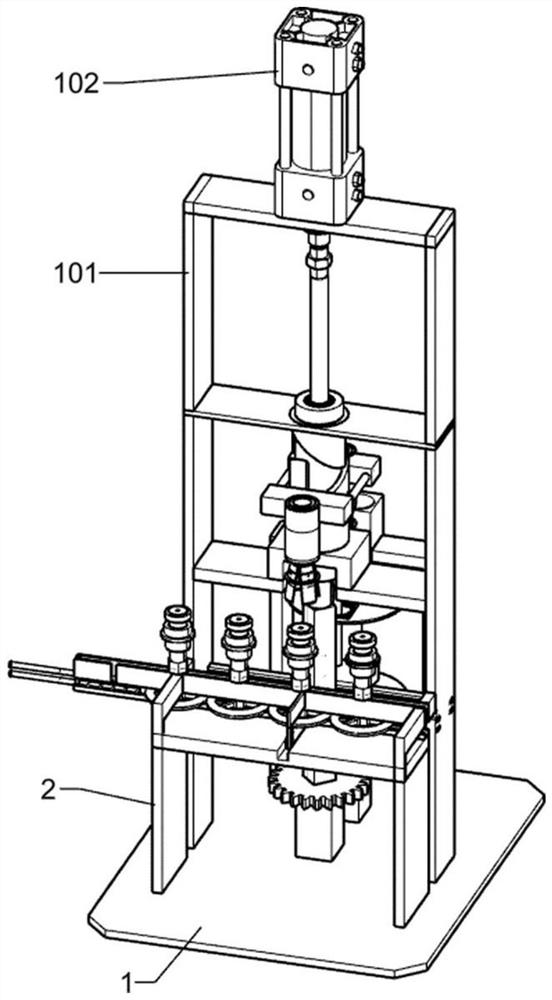
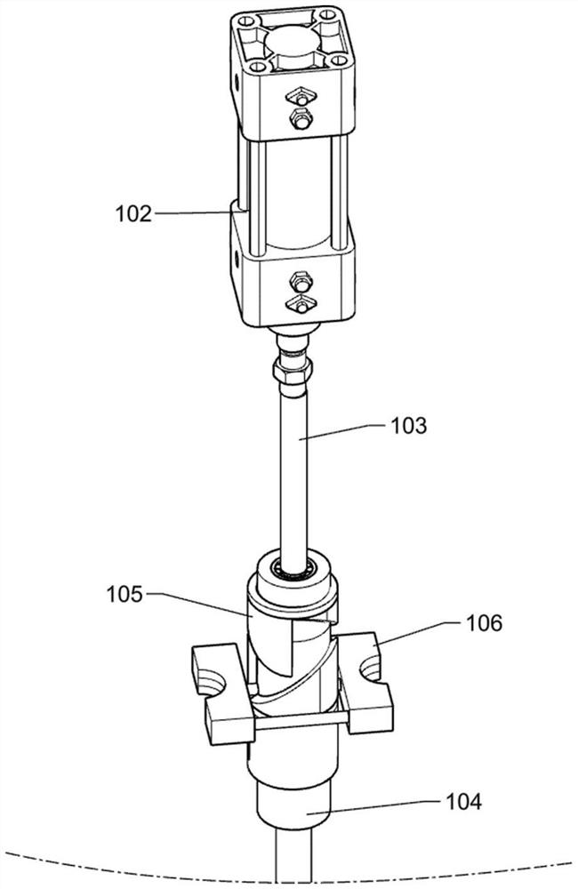
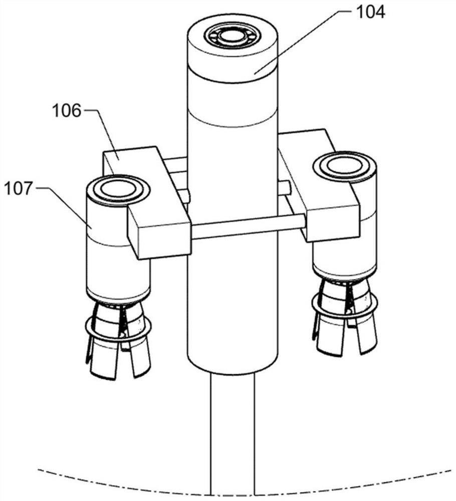
[0076] Such as Figure 1-6 As shown, a water conservancy pipeline shut-off valve assembly device includes a bottom plate 1, a main frame 101, a double gear rod 1011, a cylinder 102, a long shaft 103, a sliding column 104, a slotted pipe 105, a semicircular clamp 106, and a small sleeve 107 , small cylinder 108, small spring 109, groove plate 110, thin tube 111, thin rod 1110, round handle 112, short round tube 113, support groove rod 114, rectangular pole 115, square frame support 116, cross-shaped chute 117, connection block 118, slotted round block 119, connector 120, short straight rod 121, short round pin 122, connection concave block 123, thin spring 124 and clamping piece 125, bottom plate 1 is arranged at the bottom, main frame 101 Fixedly connected directly above the base plate 1, there is a groove in the middle of the upper panel of the workbench 2, the workbench 2 is fixedly connected to the front side of the base plate 1, the two sides of the workbench 2 extend to b...

Embodiment 2

[0079] Such as Figure 7-8 As shown, a water conservancy pipeline shut-off valve assembly device includes a workbench 2, a limit groove baffle 201, a push rod 3, a long spring 301, a bow-shaped clamping plate 4, a prismatic rotating rod 5, a cam 501, and a connecting rod 502 and short spring 503, the limit groove baffle plate 201 left front and the middle part respectively have a hole groove, the limit groove baffle plate 201 is fixedly connected to the rear end of the workbench 2 upper surface, the limit groove baffle plate 201 Pass through both sides of the workbench 2 and be in the middle of the workbench 2 and the main frame 101. The push rod 3 is slidably connected to the inner side of the left part of the limit groove baffle plate 201. The long spring 301 is sleeved on the push rod 3. The left end of the long spring 301 is in contact with the main frame 101. The limit groove baffle plate 201 contacts, and a slider is connected to the lower part of the arc clamp plate 4, ...

Embodiment 3

[0082] Such as Figure 9 As shown, a water conservancy pipeline shut-off valve assembly device includes a T-shaped bracket 6, a recess 601, a first gear 602, a second gear 603, a rotating column 604, a disc 605, a boss 606, a receiving tray 607, The bin 608, the limit plate 609 and the touch lever 610, two T-shaped brackets 6 are symmetrically arranged, the T-shaped bracket 6 is fixedly connected to the back side of the bottom plate 1, and the recess 601 is fixed to the connecting plate on the back side of the bottom plate 1 The concave seat 601 is located in the middle of the T-shaped bracket 6 and the main frame 101, the prismatic rotating rod 5 is rotatably connected to the front end of the concave seat 601, the first gear 602 is set on the lower end of the prismatic rotating rod 5, and the second gear 603 is rotatably connected to the concave On the rear side of the seat 601, the second gear 603 meshes with the first gear 602, the lower end of the rotating column 604 passe...


PUM


Abstract

The invention relates to the field of water conservancy pipeline valve body machining, in particular to a water conservancy pipeline stop valve assembling device. The invention aims to solve the technical problem of providing the water conservancy pipeline stop valve assembling device which can accurately and moderately assemble a stop valve and a gasket, and is in accurate in positioning and highin assembling efficiency. According to the technical scheme, the water conservancy pipeline stop valve assembling device comprises a bottom plate, a main rack, double shift levers and an air cylinder; and the bottom plate is arranged at the bottommost portion, the main rack is fixedly connected over the bottom plate, the air cylinder is fixedly connected to the uppermost end of the main rack, anda piston rod of the air cylinder penetrates through a baffle at the upper end of the main rack and extends downwards. According to the water conservancy pipeline stop valve assembling device, the aircylinder, a slotted pipe, a material taking and placing device and the like are additionally arranged, the air cylinder can complete the gasket taking action and the gasket assembling action after stretching out and drawing back by one cycle, and therefore the gasket assembling speed of the stop valve is greatly increased.

Description

technical field [0001] The invention relates to the field of processing a valve body of a water conservancy pipeline, in particular to an assembly device for a stop valve of a water conservancy pipeline. Background technique [0002] Globe valve, also known as cut-off valve, is a forced sealing valve, so when the valve is closed, pressure must be applied to the disc to force the sealing surface not to leak. When the medium enters the valve from the bottom of the disc, the resistance that the operating force needs to overcome is the friction between the valve stem and packing and the thrust generated by the pressure of the medium. The force to close the valve is greater than the force to open the valve, so the valve stem The diameter of the valve must be large, otherwise the failure of the valve stem to bend will occur. The tightness of the stop valve is particularly important, so the stop valve gasket must be installed correctly and moderately on the sealing surface, not de...

Claims


Application Information

Patent Timeline
Patent Type & Authority Applications(China)
IPC IPC(8): B23P19/08
CPCB23P19/08
Inventor 丁红乐
Owner 丁红乐
Why Eureka
Try Eureka