Filler, water treatment device and water treatment method
A water treatment device and water treatment technology, which are used in biological treatment devices, water treatment parameter control, biological water/sewage treatment, etc., and can solve the problems of large floor space and low biochemical treatment efficiency.
Inactive Publication Date: 2021-02-09
SHENZHEN UNIVERSILICON ENVIRONMENTAL SCI & TECH CO LTD
0 Cites 0 Cited by
AI-Extracted Technical Summary
Problems solved by technology
[0002] At present, the most typical water treatment process used to oxidize oxygen-consuming pollutants such as ammonia nitrogen and organic matter in water bodies is the application of biofilm methods. The existing equipment for biofilm methods mainly includes contact o...
Method used
Compared with the traditional aeration method, the filler 100 adopted in the water treatment method of the present application has oxygen permeability and liquid resistance, when the water body flows through the first flow space 130 where the biofilm is located and When one of the second flow spaces 140 and the air flow through the other of the first flow space 130 and the second flow space 140, the oxygen-consuming pollutants in the water body will flow from the outside of the biofilm (the biofilm is away from One side of the filler 100) diffuses toward the inner side of the biofilm (the side where the biofilm is attached to the filler 100), and the oxygen molecules in the air enter the inside of the filler 100 through one of the inner side wall 110 and the outer side wall 120 of the filler 100 dissolve and diffuse, and then diffuse to the other of the inner side wall 110 and the outer side wall 120 of the packing 100, and then desorb from the other of the inner side wall 110 and the outer side wall 120 of the packing 100 and enter the inner side wall 110 of the packing 100 In the water body and biofilm that are in contact with the other side wall 120, and diffuse from the inside of the biofilm (the side where the biofilm is attached to the filler 100) toward the outside of the biofilm (the side where the biofilm is away from the filler 100), Since the biofilm is closely attached to the inner sidewall 110 or the outer sidewall 120 of the filler 100, the distance for oxygen molecules to desorb and diffuse into the biofilm from the inner sidewall 110 or the outer sidewall 120 of the filler 100 is short, and the mass transfer efficiency is high; The consumption of oxygen molecules by the biofilm occurs on the inner and outer sides of the filler 100 (the inner side of the filler 100 is the side where the inner wall 110 of the filler 100 is located or the first flow space 130 of the filler 100, and the outer side of the filler 100 is the filler Driven by the oxygen concentration gradient on the opposite side where the outer wall 120 of the filler 100 is located or the second flow space 140 of the filler 100), the oxygen molecules in the air located on one of the inner side and the outer side of the filler 100 are continuously Oxygen molecules are supplied to the other biofilm located on the inside and outside of the filler 100 through the inner wall 110 and the outer wall 120 of the filler 100 . Therefore, the filler 100 in the present application can fully and quickly provide the biofilm with the oxygen molecules needed to degrade the oxygen-consuming pollutants in the water body. At the same time, the space utilization rate of the first flow space 130 and the second flow space 140 of the packing 100 in the present application is high, the floor area is small, and it has the advantages of simple structure, easy implementation, and high biochemical treatment efficiency, and does not require Traditional aeration equipment saves energy consumption.
Compared with the traditional aeration method, the filler 100 in the present application has oxygen permeability and liquid resistance, when the water body flows through the first flow space 130 and the second flow space where the biofilm is located 140, and the air flows through the other of the first flow space 130 and the second flow space 140, the oxygen-consuming pollutants in the water body will flow from the outside of the biofilm (the side of the biofilm away from the filler 100) ) diffuses toward the inner side of the biofilm (the side where the biofilm is attached to the filler 100), and the oxygen molecules in the air are dissolved and diffused into the filler 100 through one of the inner sidewall 110 and the outer sidewall 120 of the filler 100, and then Diffused to the other of the inner side wall 110 and the outer side wall 120 of the packing 100, and then desorbed from the other of the inner side wall 110 and the outer side wall 120 of the packing 100 and entered into the inner side wall 110 and the outer side wall 120 of the packing 100 In another contacted water body and biofilm, and spread from the inside of the biofilm (the side where the biofilm is attached to the filler 100) to the outside of the biofilm (the side where the biofilm is away from the filler 100), because the biofilm is close to On the inner sidewall 110 or the outer sidewall 120 of the filler 100, the distance for oxygen molecules to desorb and diffuse into the biofilm from the inner sidewall 110 or the outer sidewall 120 of the filler 100 is short, and the mass transfer efficiency is high; consumption, on the inner and outer sides of the packing 100 (the inner side of the packing 100 is the ...
Abstract
The invention discloses a filler, a water treatment device and a water treatment method. The filler has oxygen permeability and liquid resistance, and comprises inner side walls and outer side walls opposite to the inner side walls, wherein the inner side walls of the filler define a first overflowing space through enclosure, and second overflowing space is arranged outside the outer side walls ofthe filler. When a water body flows through the first overflowing space and air flows through the second overflowing space, the inner side walls of the filler can allow a biological membrane to growin an attached mode; and the air flowing through the second overflowing space can enter the filler through the outer side walls of the filler for dissolving and diffusion, then is diffused to the inner side walls of the filler, then is desorbed from the inner side walls of the filler and enters the first overflowing space to provide oxygen required by growth and metabolism of the biological membrane, so the biological membrane biodegrades oxygen-consuming pollutants in the water body flowing through the first overflowing space. The filler provided by the invention has the advantages of energyconsumption saving, small occupied area and high biochemical treatment efficiency.
Application Domain
Water treatment parameter controlTreatment using aerobic processes +4
Technology Topic
PollutantSmall footprint +7
Image
Examples
- Experimental program(1)
Example Embodiment
[0068] The following will clearly and completely describe the technical solutions in the embodiments of the present invention with reference to the accompanying drawings in the embodiments of the present invention. Obviously, the described embodiments are only part of the embodiments of the present invention, not all of them. Based on the embodiments of the present invention, all other embodiments obtained by persons of ordinary skill in the art without creative efforts fall within the protection scope of the present invention.
[0069] It should be noted that all directional indications (such as up, down, left, right, front, back...) in the embodiments of the present invention are only used to explain the relationship between the components in a certain posture (as shown in the accompanying drawings). Relative positional relationship, movement conditions, etc., if the specific posture changes, the directional indication will also change accordingly.
[0070] In addition, the descriptions involving "first", "second" and so on in the present invention are only for descriptive purposes, and should not be understood as indicating or implying their relative importance or implicitly indicating the quantity of the indicated technical features. Thus, the features defined as "first" and "second" may explicitly or implicitly include at least one of these features. In addition, "and/or" in the full text includes three solutions, taking A and/or B as an example, including A technical solution, B technical solution, and a technical solution that A and B satisfy at the same time; in addition, between the various embodiments The technical solutions can be combined with each other, but it must be based on the realization of those skilled in the art. When the combination of technical solutions is contradictory or cannot be realized, it should be considered that the combination of technical solutions does not exist, and it is not required by the present invention. within the scope of protection.
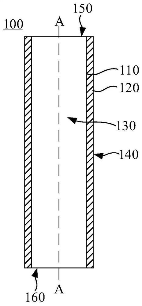
[0071] like figure 1 As shown, the present application provides a filler 100, the filler 100 has oxygen permeability and liquid resistance, the filler 100 includes an inner wall 110 and an outer wall 120 opposite to the inner wall 110, the inner wall 110 of the filler 100 surrounds A first flow space 130 is formed, and a second flow space 140 is provided outside the outer wall 120 of the filler 100. The first flow space 130 is used for the flow of one of the air and the water body to be treated to pass through, and the second flow space 140 The flow space 140 is used for the flow of the other of air and the body of water to be treated to pass through.
[0072] When the water body flows through the first flow space 130 and the air flows through the second flow space 140, the inner wall 110 of the filler 100 can support the growth of biofilm, and the oxygen molecules in the air flowing through the second flow space 140 can Enter the packing 100 through the outer wall 120 of the packing 100 to dissolve and diffuse, then diffuse to the inner wall 110 of the packing 100, and then desorb from the inner wall 110 of the packing 100 and enter the first flow space 130 to provide growth and metabolism for the biofilm Oxygen required for the biofilm to biodegrade the aerobic pollutants in the water flowing through the first overflow space 130 .
[0073] When the water body flows through the second flow space 140 and the air flows through the first flow space 130, the outer wall 120 of the filler 100 can support the growth of biofilm, and the oxygen molecules in the air flowing through the first flow space 130 can Through the inner wall 110 of the packing 100, it enters the inside of the packing 100 to dissolve and diffuse, then diffuses to the outer wall 120 of the packing 100, and then desorbs from the outer wall 120 of the packing 100 and enters the second flow space 140 to provide growth and metabolism for the biofilm. Oxygen required for the biofilm to biodegrade the aerobic pollutants in the water flowing through the second flow space 140 .
[0074]Specifically, the oxygen permeability of the filler 100 means that the inner sidewall 110 or the outer sidewall 120 of the filler 100 contacts the air and absorbs oxygen molecules in the air. The side where the inner wall 110 is located or the first flow space 130 of the packing 100, and the outside of the packing 100 is the opposite side where the outer wall 120 of the packing 100 is located or the second flow space 140 of the packing 100). Driven by the gradient, the oxygen molecules in the air adsorbed by one of the inner sidewall 110 and the outer sidewall 120 of the filler 100 dissolve and diffuse inside the filler 100, and then diffuse to the other side of the inner sidewall 110 and the outer sidewall 120 of the filler 100. One, and then desorb from the other of the inner side wall 110 and the outer side wall 120 of the packing 100 and enter the water body and biofilm in contact with the other of the inner side wall 110 and the outer side wall 120 of the packing 100, thereby realizing Oxygen molecules in the air enter the second flow space 140 of the packing 100 from the first flow space 130 of the packing 100 , or enter the first flow space 130 of the packing 100 from the second flow space 140 of the packing 100 .
[0075] The liquid resistance of the packing 100 means that water cannot pass through the inner wall 110 and the outer wall 120 of the packing 100 in liquid form, thereby preventing water from entering the second flow space 130 of the packing 100 from the first flow space 130 of the packing 100 140, or enter the first flow space 130 of the packing 100 from the second flow space 140 of the packing 100.
[0076] The filler 100 provided by this application has oxygen permeability and liquid resistance. When the water body flows through the first flow space 130 and the air flows through the second flow space 140, the inner wall 110 of the filler 100 can allow biofilm to attach and grow. , the oxygen molecules in the air flowing through the second flow space 140 can enter the inside of the packing 100 to dissolve and diffuse through the outer wall 120 of the packing 100, and then diffuse to the inner wall 110 of the packing 100, and then desorb from the inner wall 110 of the packing 100. Attached to the first flow space 130 to provide the biofilm with the oxygen needed for growth and metabolism, so that the biofilm can biodegrade the oxygen-consuming pollutants in the water flowing through the first flow space 130, thereby effectively removing the water body The effect of pollutants such as ammonia nitrogen and organic matter in the water; when the water body flows through the second flow space 140 and the air flows through the first flow space 130, the outer wall 120 of the packing 100 can support the growth of biofilm, and flow through the first flow space 130. Oxygen molecules in the air in the overflow space 130 can pass through the inner side wall 110 of the packing 100 into the inside of the packing 100 for dissolution and diffusion, then diffuse to the outer side wall 120 of the packing 100, and then desorb from the outer side wall 120 of the packing 100 and enter the second The overflow space 140 provides the biofilm with the oxygen required for growth and metabolism, so that the biofilm can biodegrade the oxygen-consuming pollutants in the water flowing through the second overflow space 140, thereby effectively removing ammonia nitrogen and organic matter in the water. The role of other pollutants;
[0077] Compared with the traditional aeration method, the filler 100 in this application has oxygen permeability and liquid resistance, when the water body flows through the first flow space 130 and the second flow space 140 where the biofilm is located, One of them, and when the air flows through the other of the first flow space 130 and the second flow space 140, the oxygen-consuming pollutants in the water flow from the outside of the biofilm (the side of the biofilm away from the packing 100) toward the biofilm. The inner side of the film (the side where the biofilm is attached to the filler 100) diffuses, and the oxygen molecules in the air enter the filler 100 through one of the inner sidewall 110 and the outer sidewall 120 of the filler 100 to dissolve and diffuse, and then diffuse to the filler The other of the inner side wall 110 and the outer side wall 120 of the packing 100 is then desorbed from the other of the inner side wall 110 and the outer side wall 120 of the packing 100 and enters into the other of the inner side wall 110 and the outer side wall 120 of the packing 100 In the contacted water body and biofilm, and spread from the inside of the biofilm (the side where the biofilm is attached to the filler 100) to the outside of the biofilm (the side where the biofilm is away from the filler 100), because the biofilm is close to the filler 100 Therefore, the distance for oxygen molecules to desorb from the inner wall 110 or outer wall 120 of the filler 100 and diffuse into the biofilm is short, and the mass transfer efficiency is high; at the same time, as the biofilm consumes oxygen molecules, On the inner and outer sides of the packing 100 (the inner side of the packing 100 is the side where the inner side wall 110 of the packing 100 is located or the first flow space 130 of the packing 100, and the outer side of the packing 100 is the opposite side where the outer side wall 120 of the packing 100 is located. Driven by the oxygen concentration gradient on the other side of the packing 100 or the second overflow space 140 of the packing 100), the oxygen molecules in the air located on one of the inner side and the outer side of the packing 100 continuously permeate the inner side wall of the packing 100 110 and the outer wall 120 supply oxygen molecules to the other biofilm located on the inside and outside of the packing 100. Therefore, the packing 100 in the present application can provide the biofilm with oxygen-consuming pollutants in the degraded water body sufficiently and rapidly. required oxygen molecules; at the same time, the space utilization rate of the first flow space 130 and the second flow space 140 of the filler 100 in the present application is high, the floor area is small, and it has the advantages of simple structure, easy implementation, and high biochemical treatment efficiency Advantages, and does not require traditional aeration equipment, saving energy consumption.
[0078] Referring to Table 1, the volumetric efficiency of the water treatment process using the filler 100 of the present application and the traditional water treatment process for the treatment of oxygen-consuming pollutants in the water body is compared:
[0079]
[0080] Table 1
[0081] In one embodiment, the filler 100 can be made of, but not limited to, silicone rubber. Silicone rubber refers to a vulcanized polysiloxane whose main chain is composed of silicon atoms and oxygen atoms alternately and organic groups are attached to the silicon atoms. The polymer material formed after the action; more specifically, the filler 100 can be made of dimethyl silicone rubber or fluorosilicone rubber; it can be understood that as long as the filler can realize the function of oxygen permeability and liquid resistance, it should be suitable for this application. Example of application.
[0082] Specifically, the oxygen in the air can be transferred between the first flow space 130 and the second flow space 140 by relying on the microscopic molecular units constituting the filler 100 as a transfer medium.
[0083] In one embodiment, the vertical distance between the inner side wall 110 and the outer side wall 120 of the filler 100 is smaller than a first predetermined value, so as to improve the flow of oxygen molecules in the air between the first flow space 130 and the second flow space 140. transfer efficiency between them. In one embodiment, preferably, the first preset value is 1mm, that is, the vertical distance between the inner sidewall 110 and the outer sidewall 120 of the filler 100 is less than 1mm.
[0084] In one embodiment, the first flow space 130 extends along the axial direction of the packing 100 and is used for the flow of water to be treated to pass through, and the second flow space 140 is used for the flow of air to pass through; the packing 100 The inner side wall 110 can be used for the attachment and growth of biofilm, and the minimum size of the first flow space 130 in the direction perpendicular to the axial direction of the packing 100 is smaller than the second preset value, so that the first flow space entering the packing 100 The water body in 130 can flow along the axial direction of packing 100 . It should be noted that, for ease of understanding, the axial direction of the filler 100 is defined as figure 1 and Figure 4 A-A direction indicated in .
[0085] In this solution, the water body can flow through the first flow space 130 extending along the axial direction of the packing 100, the air can flow through the second flow space 140, and the first flow space 130 is perpendicular to the axial direction of the packing 100. The minimum size in the direction of the packing 100 is smaller than the second preset value, which can ensure that the water entering the first overflow space 130 of the packing 100 can flow along the axial direction of the packing 100 in the form of pushing flow, which is beneficial to realize the flow through the first flow space 130. The water body in the first overflow space 130 is fully in contact with the biofilm grown on the inner wall 110 of the filler 100, so that the biofilm grown on the inner wall 110 of the filler 100 can fully realize the water body flowing through the first overflow space 130 The biodegradation of oxygen-consuming pollutants in the water body can effectively improve the biochemical treatment efficiency of the water body, and at the same time, the flow uniformity of the water body relative to the first flow space 130 can be improved to a certain extent; The impact force is greater than the impact force of the air on the packing 100. Compared with the setting method of making the water flow through the second flow space 140 and the air flow through the first flow space 130, by making the water flow through the first flow space space 130, and make air flow through the second flow space 140, so that the water flowing through the first flow space 130 can apply a second flow space 140 towards the packing 100 to the inner wall 110 of the packing 100 (ie The impact force in the direction of the outside of the packing 100 can fully resist the impact force of the air applied to the outer wall 120 of the packing 100 , thereby ensuring the structural integrity of the packing 100 and avoiding structural deformation of the packing 100 .
[0086] In one embodiment, the second preset value is 5 cm, and the minimum dimension of the first flow space 130 in a direction perpendicular to the axial direction of the filler 100 is less than 5 cm.
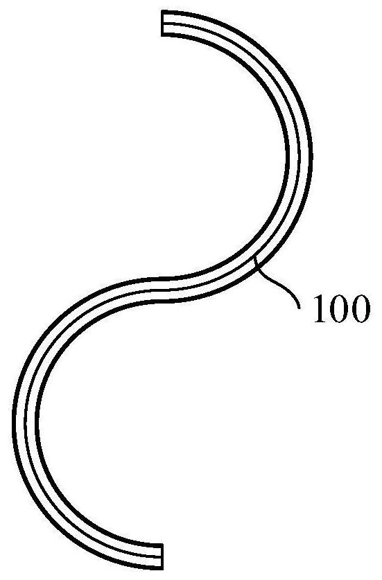
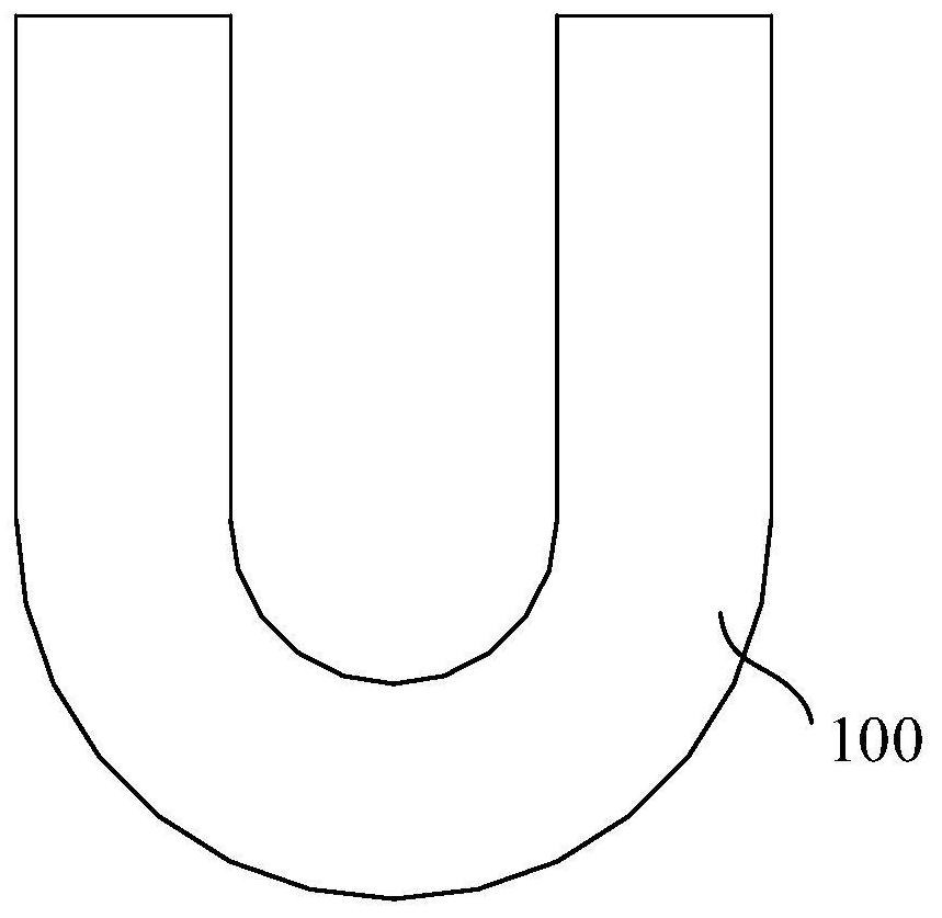
[0087] like figure 1 As shown, in one embodiment, the filler 100 is a tubular structure. In an embodiment, the filler 100 may be a circular tube structure, an elliptical tube structure or a polygonal tube structure. Further, the filler 100 may be a straight pipe structure or a curved pipe structure. Specifically, such as figure 2 and image 3 As shown, the filler 100 can be an S-bend structure or a U-bend structure. In one embodiment, when the packing 100 is a straight pipe structure, the minimum size of the first flow space 130 in the direction perpendicular to the axial direction of the packing 100 is the minimum size of the first flow space 130 in the radial direction, that is The radial minimum size of the first flow space 130 is smaller than a second preset value.
[0088] In another embodiment, such as Figure 4 As shown, the packing 100 can be a plate structure, and the packing 100 includes a first side wall 121, a second side wall 122, a third side wall 123 and a fourth side wall 124, and the first side wall 121 is opposite to the second side wall 122. Set, the third side wall 123 is opposite to the fourth side wall 124, and the third side wall 123 and the fourth side wall 124 are connected between the first side wall 121 and the second side wall 122, the first side wall 121, The side of the second side wall 122, the third side wall 123 and the fourth side wall 124 facing the first flow space 130 jointly constitute the inner side wall 110 of the filler 100, the first side wall 121, the second side wall 122, the third side wall The side of the side wall 123 and the fourth side wall 124 facing the second flow space 140 together constitute the outer wall 120 of the packing 100 . Specifically, the minimum size of the first flow space 130 in the direction perpendicular to the axial direction of the packing 100 is the distance between the first side wall 121 and the second side wall 122 in the direction perpendicular to the axial direction of the packing 100 , that is, the distance between the first sidewall 121 and the second sidewall 122 in a direction perpendicular to the axial direction of the filler 100 is smaller than a second preset value.
[0089] Specifically, the first side wall 121 is arranged parallel to the second side wall 122, the third side wall 123 is arranged parallel to the fourth side wall 124, and the third side wall 123 is vertically connected to the first side wall 121 and the second side wall 122. , the fourth sidewall 124 is vertically connected to the first sidewall 121 and the second sidewall 122 .
[0090] In one embodiment, the first sidewall 121 , the second sidewall 122 , the third sidewall 123 and the fourth sidewall 124 have the same thickness.
[0091] like figure 1 As shown, in one embodiment, the two ends of the filler 100 are respectively provided with a first opening 150 and a second opening 160, the first opening 150 and the second opening 160 are both connected to the first flow space 130, and the first opening 150 and the second opening 160 are respectively used for water or air to flow into and out of the first flow space 130 .
[0092] In an embodiment, the present application also provides a water treatment device, the water treatment device includes the above packing 100 . The concrete structure of this packing 100 is with reference to above-mentioned embodiment, because this water treatment device has adopted all technical schemes of all embodiments of above-mentioned packing 100, therefore at least has all beneficial effects brought by the technical solutions of the embodiment of above-mentioned packing 100, No more details here.
[0093] like Figure 5 and Image 6 As shown, in one embodiment, the above-mentioned water treatment device is provided with a plurality of fillers 100 , and the plurality of fillers 100 together constitute a filler assembly 101 . In one embodiment, multiple fillers 100 are arranged side by side, and there is a gap between any two adjacent fillers 100 . In one embodiment, multiple fillers 100 are connected to each other, and the connection between multiple fillers 100 can be sequentially connected in series or connected in series or parallel with each other according to the actual situation, and the specific arrangement method can be reasonably selected according to the actual situation.
[0094] In one embodiment, the packing assembly 101 further includes a connecting piece 102 through which a plurality of packings 100 are connected together. In one embodiment, the connecting member 102 is connected between two adjacent fillers 100 to connect multiple fillers 100 together.
[0095] like Figure 7 As shown, in one embodiment, the connector 102 has an inner cavity 1022 capable of accommodating air, the packing 100 is accommodated in the inner cavity 1022, and protrudes out of the inner cavity 1022 through both sides of the connector 102, and a plurality of fillers 100 are opposite to each other. The connectors 102 are arranged side by side. When the packing assembly 101 is placed in the water body to be treated, the water body can flow through the first overflow space 130 of the packing 100, and the air in the inner cavity 1022 can flow through the second overflow space of the packing 100. Space 140, so that the biofilm grown on the inner side wall 110 of each packing 100 can biodegrade the oxygen-consuming pollutants in the water body, and the connecting piece 102 can also block the water body to prevent the water body from passing through the inner chamber 1022 relative to the second wall of the packing 100. The input of flow space 140 .
[0096] like Figure 8 and Figure 9 As shown, in one embodiment, the packing assembly 101 further includes a first transmission assembly 170 and a second transmission assembly 180, the first transmission assembly 170 communicates with the first end of the first flow space 130 of each packing 100, and the second The transmission assembly 180 communicates with the second end of the first flow space 130 of each packing 100, and one of the water body and the air to be treated can flow into the first flow space 130 of each packing 100 through the first transmission assembly 170 , and then flow out to the outside of the first flow space 130 of each filler 100 through the second transmission component 180 .
[0097] like Figure 8 and Figure 9 As shown, in one embodiment, the first transmission assembly 170 includes a connected first pipe body 172 and a first transmission member 174, the first transmission member 174 is a hollow structure, and the first transmission member 174 is far away from the first pipe body 172 One end communicates with the first end of the first flow space 130 of each filler 100. The second transmission assembly 180 includes a second pipe body 182 connected to a second transmission member 184. The second transmission member 184 is a hollow structure. One end of the second transmission member 184 away from the second pipe body 182 communicates with the second end of the first flow space 130 of each packing 100, and one of the water body and the air to be treated can pass through the first pipe body 172, the first transmission The member 174 flows into the first flow space 130 of each packing 100 , and then flows out of the first flow space 130 of each packing 100 through the second transmission member 184 and the second pipe body 182 .
[0098] In one embodiment, the above-mentioned water treatment device is provided with a plurality of packing assemblies 101, and the multiple packing assemblies 101 are connected; specifically, the connection between the multiple packing assemblies 101 can be sequentially connected in series or connected in series according to specific conditions. Or parallel connection, the specific setting method can be reasonably selected according to the actual situation.
[0099] like Figure 10 As shown, in one embodiment, the above-mentioned water treatment device also includes a reaction tank 103, the reaction tank 103 is used to accommodate the water body to be treated, the filler 100 is accommodated in the reaction tank 103, and the water body in the reaction tank 103 can flow through the second Through the flow space 140 , air can flow through the first flow space 130 , so that the biofilm grown on the outer wall 120 of the filler 100 can biodegrade the aerobic pollutants in the water body in the reaction tank 103 .
[0100] In one embodiment, the packing 100 can directly contact the air in the external environment, so as to realize the input of the air in the external environment to the first flow space 130 or the second flow space 140, so that the inner wall 110 or the outer side of the packing 100 The biofilm grown on the wall 120 can use the oxygen molecules in the air in the external environment as the oxygen needed for growth and metabolism to realize the biodegradation of aerobic pollutants in the water body, thereby avoiding the need for users to set additional aeration equipment to Oxygen is injected into the water body to effectively reduce energy consumption.
[0101] like Figure 11 As shown, in one embodiment, when the above-mentioned water treatment device is provided with a plurality of fillers 100 and the first overflow space 130 of the filler 100 is used for the flow of the water body to be treated to pass through, the second overflow space of the filler 100 140 is used for the flow of air to pass through, the water treatment device also includes a first transmission unit 104 and a second transmission unit 105, the first transmission unit 104 communicates with the first end of the first flow space 130 of each filler 100, The second transmission unit 105 communicates with the second end of the first flow space 130 of each packing 100, the first transmission unit 104 is used for inputting the water to be treated into the first flow space 130 of each packing 100, and the second transmission The unit 105 is used for outputting the treated water output from the first overflow space 130 of each filler 100 to the outside.
[0102] In one embodiment, the first transmission unit 104 includes a first connecting pipe 1041 and a second connecting pipe 1042, the first connecting pipe 1041 communicates with the first end of the first flow space 130 of each packing 100, specifically, the second A connecting pipe 1041 is connected to the first opening 150 of each filler 100, and the second connecting pipe 1042 is connected to the first connecting pipe 1041. The water body to be treated can be input to each of the packing materials through the second connecting pipe 1042 and the first connecting pipe 1041 in sequence. The first overflow space 130 of the filler 100 . In one embodiment, the first transmission unit 104 further includes a first control valve 1043, the first control valve 1043 is disposed on the second connecting pipe 1042, and the first control valve 1043 is used to control the conduction and connection of the second connecting pipe 1042. disconnect, and then control the input of the water body relative to the first flow space 130 of each filler 100 .
[0103] Further, the second transmission unit 105 includes a third connecting pipe 1051 and a fourth connecting pipe 1052, the third connecting pipe 1051 communicates with the second end of the first flow space 130 of each filler 100, specifically, the third connecting pipe 1051 is connected to the second opening 160 of each packing 100, the fourth connecting pipe 1052 is connected to the third connecting pipe 1051, and the treated water output from the first overflow space 130 of each packing 100 can pass through the third connecting pipe 1051 in turn. , The fourth connecting pipe 1052 is output to the outside. In one embodiment, the second transmission unit 105 further includes a second control valve 1053, the second control valve 1053 is disposed on the fourth connecting pipe 1052, and the second control valve 1053 is used to control the conduction and connection of the fourth connecting pipe 1052. disconnect, and then control the output of the treated water output from the first overflow space 130 of each filler 100 relative to the outside.
[0104] In one embodiment, the above-mentioned water treatment device further includes a water storage tank 106, the water storage tank 106 is used to accommodate the water body to be treated, and the end of the second connecting pipe 1042 away from the first connecting pipe 1041 extends into the water storage tank 106, and the water storage tank The water output from 106 can be input to the first flow space 130 of each filler 100 through the second connecting pipe 1042 and the first connecting pipe 1041 in sequence.
[0105] In one embodiment, the present application also provides a water treatment method, the water treatment method comprising:
[0106] S100, provide filler 100.
[0107] S200, introducing the water body to be treated into the first overflow space 130 and air into the second overflow space 140, so that the water body flows through the first overflow space 130 and the air flows through the second overflow space 140, In this way, the inner wall 110 of the filler 100 forms a biofilm, and the oxygen molecules in the air flowing through the second flow space 140 enter the filler 100 through the outer wall 120 of the filler 100 to dissolve and diffuse, and then diffuse to the inside of the filler 100. The inner sidewall 110 then desorbs from the inner sidewall 110 of the filler 100 and enters the first flow space 130 to provide the oxygen required for the growth and metabolism of the biofilm.
[0108] S300, the biofilm grown on the inner wall 110 of the filler 100 biodegrades the aerobic pollutants in the water flowing through the first flow space 130 .
[0109] In one embodiment, after performing the step S100 of providing the filler 100, the water treatment method includes:
[0110] S400, introducing water to be treated into the second flow space 140 and air into the first flow space 130, so that the water flows through the second flow space 140 and the air flows through the first flow space 130, In this way, the outer wall 120 of the filler 100 forms a biofilm, and the oxygen molecules in the air flowing through the first flow space 130 enter the inner wall 110 of the filler 100 to dissolve and diffuse into the filler 100, and then diffuse to the inside of the filler 100. The outer wall 120 then desorbs from the outer wall 120 of the filler 100 and enters the second flow space 140 to provide the oxygen required for the growth and metabolism of the biofilm.
[0111] S500, biodegrading the aerobic pollutants in the water flowing through the second flow space 140 through the biofilm grown on the outer wall 120 of the filler 100 .
[0112] In the water treatment method provided by this application, since the filler 100 used has oxygen permeability and liquid resistance, when the water body flows through the first flow space 130 and the air flows through the second flow space 140, the inner wall 110 of the filler 100 The oxygen molecules in the air flowing through the second overflow space 140 can enter the inside of the filler 100 to dissolve and diffuse through the outer wall 120 of the filler 100, and then diffuse to the inner wall 110 of the filler 100, and then from the filler The inner wall 110 of 100 desorbs and enters the first flow space 130 to provide the biofilm with the oxygen required for growth and metabolism, so that the biofilm can biodegrade the oxygen-consuming pollutants in the water flowing through the first flow space 130 , so as to effectively remove pollutants such as ammonia nitrogen and organic matter in the water body; when the water body flows through the second flow space 140 and the air flows through the first flow space 130, the outer wall 120 of the filler 100 can allow biofilm to adhere Oxygen molecules in the air flowing through the first overflow space 130 can enter the inside of the packing 100 to dissolve and diffuse through the inner side wall 110 of the packing 100, and then diffuse to the outer side wall 120 of the packing 100, and then from the outer side wall 120 of the packing 100 Desorb and enter the second flow space 140 to provide the biofilm with the oxygen needed for growth and metabolism, so that the biofilm can biodegrade the oxygen-consuming pollutants in the water flowing through the second flow space 140, thereby achieving effective removal The role of pollutants such as ammonia nitrogen and organic matter in the water body;
[0113]Compared with the traditional aeration method, the filler 100 used in the water treatment method of this application has oxygen permeability and liquid resistance, when the water body flows through the first flow space 130 and the second flow space where the biofilm is located, When one of the flow spaces 140 and the air flow through the other of the first flow space 130 and the second flow space 140, the oxygen-consuming pollutants in the water body will flow from the outside of the biofilm (the side of the biofilm away from the packing 100 One side) diffuses toward the inner side of the biofilm (the side where the biofilm is attached to the filler 100), and the oxygen molecules in the air enter the filler 100 through one of the inner sidewall 110 and the outer sidewall 120 of the filler 100 to dissolve and diffuse , and then diffuse to the other of the inner side wall 110 and the outer side wall 120 of the packing 100, and then desorb from the other of the inner side wall 110 and the outer side wall 120 of the packing 100 and enter into the inner side wall 110 and the outer side wall of the packing 100 In another contacted water body and biofilm in 120, and diffuse from the inside of the biofilm (the side where the biofilm is attached to the filler 100) toward the outside of the biofilm (the side where the biofilm is away from the filler 100), due to the biofilm Close to the inner wall 110 or the outer wall 120 of the packing 100, so the distance for oxygen molecules to desorb from the inner wall 110 or the outer wall 120 of the packing 100 and diffuse into the biofilm is short, and the mass transfer efficiency is high; Oxygen molecules are consumed on the inner and outer sides of the filler 100 (the inner side of the filler 100 is the side where the inner wall 110 of the filler 100 is located or the first flow space 130 of the filler 100, and the outer side of the filler 100 is the outer side of the filler 100 Driven by the oxygen concentration gradient on the opposite side where the wall 120 is located or the second flow space 140 of the packing 100), the oxygen molecules in the air located on one of the inner side and the outer side of the packing 100 continuously permeate The inner side wall 110 and the outer side wall 120 of the filler 100 supply oxygen molecules to the other biofilm located on the inner side and the outer side of the filler 100 . Therefore, the filler 100 in the present application can fully and quickly provide the biofilm with the oxygen molecules needed to degrade the oxygen-consuming pollutants in the water body. At the same time, the space utilization rate of the first flow space 130 and the second flow space 140 of the packing 100 in the present application is high, the floor area is small, and it has the advantages of simple structure, easy implementation, and high biochemical treatment efficiency, and does not require Traditional aeration equipment saves energy consumption.
[0114] In one embodiment, in the step S100 of providing the filler 100, there are multiple fillers 100, and the plurality of fillers 100 together constitute the filler assembly 101, that is, the aerobic pollution in the water body is reduced by the filler assembly 101 composed of a plurality of fillers 100. Biodegradation of substances can enhance the efficiency of biochemical treatment of water bodies.
[0115] In one embodiment, the step of introducing the water body to be treated into the first flow space 130 or the second flow space 140 includes: placing the filler 100 in the water body to be treated, so as to realize the flow of the water body into the second flow space 140 , so that the biofilm grown on the outer wall 120 of the packing 100 realizes the biodegradation of the aerobic pollutants in the water body to be treated.
[0116] In one embodiment, the step of introducing the water body to be treated into the first overflow space 130 or the second overflow space 140 includes:
[0117] A packing assembly 101 is provided. The packing assembly 101 includes a plurality of packings 100 and connectors 102. The connectors 102 have an inner cavity 1022 capable of accommodating air. Outside the cavity 1022, a plurality of fillers 100 are arranged side by side relative to the connector 102, and the air in the inner cavity 1022 can flow through the second flow space 140 of the filler 100;
[0118] The packing assembly 101 is placed in the water body to be treated, so as to realize the input of the water body to the first flow space 130 of each packing 100, and then make the biofilm grown on the inner side wall 110 of each packing 100 consume oxygen in the water body Pollutants biodegrade.
[0119] In one embodiment, the step of introducing air into the first flow space 130 or the second flow space 140 includes: making the filler 100 directly contact the air in the external environment, so as to realize the air flow in the external environment to the first flow space. space 130 or the input of the second flow space 140, so that the biofilm grown on the inner wall 110 or the outer wall 120 of the filler 100 can use the oxygen molecules in the air in the external environment as the oxygen needed for growth and metabolism. The biodegradation of oxygen-consuming pollutants in the water body can avoid users from setting up additional aeration equipment to inject oxygen into the water body, effectively reducing energy consumption and material consumption.
[0120] In one embodiment, the step of making the filler 100 directly contact the air in the external environment so as to realize the input of the air in the external environment to the first flow space 130 or the second flow space 140 includes:
[0121] The ventilation device disturbs the air in the external environment to improve the fluidity of the air in the external environment, so as to accelerate the input of the air in the external environment to the first flow space 130 or the second flow space 140 to improve efficiency. In one embodiment, the ventilation device may be a fan.
[0122] In one embodiment, when the water body to be treated is located in a river course or a reservoir, the above water treatment method further includes: fixing the filler 100 at a preset position of the water body in the river course or reservoir, so as to realize the water body flowing to the second The input of the space 140 further enables the biofilm grown on the outer wall 120 of the filler 100 to realize the biodegradation of the oxygen-consuming pollutants in the water body in the river course or the reservoir.
[0123] In one embodiment, when the water body to be treated is located in a river course or a reservoir, the above water treatment method further includes:
[0124] A packing assembly 101 is provided. The packing assembly 101 includes a plurality of packings 100 and connectors 102. The connectors 102 have an inner cavity 1022 capable of accommodating air. Outside the cavity 1022, a plurality of fillers 100 are arranged side by side relative to the connector 102, and the air in the inner cavity 1022 can flow through the second flow space 140 of the filler 100;
[0125] The packing assembly 101 is fixed at the predetermined position of the water body in the river channel or the reservoir, so as to realize the input of the water body to the first flow space 130 of each packing 100, and then make the biofilm grown on the inner wall 110 of each packing 100 Realize the biodegradation of oxygen-consuming pollutants in water bodies in river courses or reservoirs.
[0126] like Figure 12 and Figure 13 As shown, in an embodiment, when the water body to be treated is located in a river course or a reservoir, the above water treatment method further includes: driving the filler 100 to move relative to the water body in the river course or reservoir through the drive assembly 107, so that the water body located in the river course or reservoir Water bodies at different locations can flow through the second flow space 140 of the filler 100 , so that the biofilm grown on the outer wall 120 of the filler 100 can biodegrade the aerobic pollutants in different locations of the river or reservoir.
[0127] In one embodiment, when the water body to be treated is located in a river channel or a reservoir, the above water treatment method further includes: providing a packing assembly 101, and driving the packing assembly 101 to move relative to the water body in the river channel or reservoir through the driving assembly 107, so that the water body located in the river channel or the reservoir Water bodies in different positions of the river course or reservoir can flow through the first flow space 130 of each filler 100, so that the biofilm grown on the inner side wall 110 of each filler 100 realizes the oxygen consumption pollution of the water body in different positions of the river course or reservoir biodegradation of substances.
[0128] In one embodiment, the driving assembly 107 may be, but not limited to, a cruise ship 108, which can float on the surface of the water body in the river channel or the reservoir, and can move relative to the water body in the river channel or the reservoir.
[0129] In one embodiment, when the cruise ship 108 drives the packing assembly 101 to move relative to the water body in the river channel or reservoir, the packing assembly 101 can be installed on the bottom of the cruise ship 108 .
[0130] In one embodiment, when the water body to be treated is a low-temperature water body, the air is hot air, so that the ambient temperature of the biofilm can reach the optimum temperature condition for the growth of the biofilm itself, so as to facilitate the growth of the biofilm in the low-temperature water body. growth, thereby improving the biofilm biodegradation efficiency of the oxygen-consuming pollutants in the low-temperature water body. The low-temperature water body is the water body whose temperature is lower than the first set value, and the hot air is the air whose temperature is higher than the second set value.
[0131] like Figure 14 and Figure 15 As shown, it should be pointed out that in another embodiment, the present application also provides a packing 200, the packing 200 has oxygen permeability and liquid resistance, the packing 200 includes a multi-layer packing wall 210, and the multi-layer packing The walls 210 are coiled together, and flow channels 211 are formed between any adjacent two layers of filler walls 210. The plurality of flow channels 211 include first flow channels 220 and second flow channels 230 that are arranged alternately from inside to outside. Each first flow channel The channels 220 are connected, and each second flow channel 230 is connected. The first flow channel 220 is used for the flow of one of the air and the water body to be treated, and the second flow channel 230 is used for the air and the water body to be treated. The flow of the other one passes through.
[0132] When the water body flows through the first flow channel 220 and the air flows through the second flow channel 230, the side of the filler wall 210 facing the first flow channel 220 can support the growth of biofilm, and the oxygen molecules in the air flowing through the second flow channel 230 It can enter the inside of the packing wall 210 to dissolve and diffuse through the side of the packing wall 210 facing the second flow channel 230, then diffuse to the side of the packing wall 210 facing the first flow channel 220, and then from the packing wall 210 toward the side of the first flow channel 220 The side desorbs and enters the first flow channel 220 to provide the biofilm with oxygen required for growth and metabolism, so that the biofilm can biodegrade the oxygen-consuming pollutants in the water flowing through the first flow channel 220 .
[0133] When the water body flows through the second flow channel 230 and the air flows through the first flow channel 220, the side of the packing wall 210 facing the second flow channel 230 can support the growth of biofilm, and the oxygen molecules in the air flowing through the first flow channel 220 It can enter the inside of the packing wall 210 to dissolve and diffuse through the side of the packing wall 210 facing the first flow channel 220, and then diffuse to the side of the packing wall 210 facing the second flow channel 230, and then from the packing wall 210 toward the side of the first flow channel 220 The side desorbs and enters the second flow channel 230 to provide the biofilm with oxygen required for growth and metabolism, so that the biofilm can biodegrade the oxygen-consuming pollutants in the water flowing through the second flow channel 230 .
[0134] The filler 200 provided by this application has oxygen permeability and liquid resistance. When water flows through the first flow channel 220 and air flows through the second flow channel 230, the side of the filler wall 210 facing the first flow channel 220 can provide biofilm Adhesion growth, the oxygen molecules in the air flowing through the second flow channel 230 can pass through the side of the filler wall 210 facing the second flow channel 230 into the inside of the filler wall 210 to dissolve and diffuse, and then diffuse to the filler wall 210 toward the first flow channel 220 Then desorb from the side of the filler wall 210 toward the first flow channel 220 and enter the first flow channel 220 to provide the biofilm with the oxygen needed for growth and metabolism, so that the biofilm can convect the water body flowing through the first flow channel 220 Oxygen-consuming pollutants are biodegraded, thereby achieving the effect of effectively removing pollutants such as ammonia nitrogen and organic matter in the water body; when the water body flows through the second flow channel 230 and the air flows through the first flow channel 220, the filler wall 210 faces the second flow channel 220. One side of the flow channel 230 can be used for biofilm attachment and growth, and the oxygen molecules in the air flowing through the first flow channel 220 can pass through the filler wall 210 toward the side of the first flow channel 220 to enter the filler wall 210 for dissolution and diffusion, and then diffuse to The filler wall 210 faces the side of the second flow channel 230, and then desorbs from the side of the filler wall 210 toward the first flow channel 220 and enters the second flow channel 230 to provide the biofilm with the oxygen required for growth and metabolism, so that the biological The membrane biodegrades the oxygen-consuming pollutants in the water flowing through the second flow channel 230, thereby achieving the effect of effectively removing pollutants such as ammonia nitrogen and organic matter in the water;
[0135]Compared with the traditional aeration method, the filler 200 in this application has oxygen permeability and liquid resistance, when the water body flows through one of the first flow channel 220 and the second flow channel 230 where the biofilm is located, and When the air flows through the other of the first flow channel 220 and the second flow channel 230, the oxygen-consuming pollutants in the water body move from the outside of the biofilm (the side of the biofilm away from the filler wall 210) to the inside of the biofilm (the side of the biofilm). attached to the side of the packing wall 210), and the oxygen molecules in the air enter the packing wall through one of the side of the packing wall 210 facing the first flow channel 220 and the side of the packing wall 210 facing the second flow channel 230 210 internal dissolution and diffusion, and then spread to the other side of the packing wall 210 facing the first flow channel 220 and the side of the packing wall 210 facing the second flow channel 230, and then from the packing wall 210 to one side of the first flow channel 220 side and the side of the packing wall 210 facing the second flow channel 230 is desorbed and enters the side of the packing wall 210 facing the first flow channel 220 and the side of the packing wall 210 facing the second flow channel 230 In another contacted water body and biofilm, and diffuse from the inside of the biofilm (the side where the biofilm is attached to the filler wall 210) toward the outside of the biofilm (the side where the biofilm is away from the filler wall 210), due to the tightness of the biofilm Stick to the side of the packing wall 210 facing the first flow channel 220 or the side of the packing wall 210 facing the second flow channel 230, so the oxygen molecules are from the side of the packing wall 210 facing the first flow channel 220 or the side of the packing wall 210 facing the second flow One side of the channel 230 desorbs and diffuses into the biofilm for a short distance, and the mass transfer efficiency is high; at the same time, as the biofilm consumes oxygen molecules, the side of the filler wall 210 facing the first flow channel 220 and the filler wall 210 facing the Driven by the oxygen concentration gradient on one side of the second flow channel 230, the oxygen in the air located on one of the side of the packing wall 210 facing the first flow channel 220 and the side of the packing wall 210 facing the second flow channel 230 Molecules continuously pass through the side of the packing wall 210 facing the first flow channel 220 and the side of the packing wall 210 facing the second flow channel 230, being located on the side of the packing wall 210 facing the first flow channel 220 and the side of the packing wall 210 facing the second flow channel 230. The biofilm on the other side of the two channels 230 supplies oxygen molecules. Therefore, the filler 200 in the present application can fully and quickly provide the biofilm with the oxygen molecules needed to degrade the oxygen-consuming pollutants in the water body; It has the advantages of high space utilization rate, small footprint, simple structure, easy implementation, and high biochemical treatment efficiency, and does not require traditional aeration equipment, saving energy consumption.
[0136] In an embodiment, the present application also provides a water treatment device, the water treatment device includes the above packing 200 . The concrete structure of this filler 200 is with reference to above-mentioned embodiment, because this water treatment device has adopted all technical schemes of all embodiments of above-mentioned filler 200, therefore at least has all beneficial effects brought by the technical scheme of the embodiment of above-mentioned filler 200, No more details here.
[0137] like Figure 16 As shown, in an embodiment, the above-mentioned water treatment device is provided with a plurality of fillers 200 , and the plurality of fillers 200 together constitute a filler assembly 201 . In one embodiment, multiple fillers 200 are arranged side by side, and there is a gap between any two adjacent fillers 200 .
[0138] In one embodiment, when the above-mentioned water treatment device is provided with a plurality of fillers 200 and the first channel 220 of the filler 200 is used for the flow of the water body to be treated, the second channel 230 of the filler 200 is used for the flow of air. When flowing through, the above-mentioned water treatment device also includes a first conveying assembly 202 and a second conveying assembly 203, the first conveying assembly 202 communicates with the first end of the first flow channel 220 of each packing 200, and the second conveying assembly 203 communicates with each packing The second end of the first flow channel 220 of 200 is connected, the first delivery assembly 202 is used to supply the water to be treated to the first flow channel 220 of each packing 200, and the second delivery assembly 203 is used to supply the first flow channel of each packing 200 The treated water body output by 220 is output to the outside.
[0139] In one embodiment, the first conveying assembly 202 includes a plurality of first auxiliary pipes 2021 and second auxiliary pipes 2022, each first auxiliary pipe 2021 communicates with the first end of the first channel 220 of each filler 200, and the second The auxiliary pipes 2022 are connected to each first auxiliary pipe 2021 , and the water body to be treated can be input to the corresponding first channel 220 of each filler 200 through the second auxiliary pipe 2022 and each first auxiliary pipe 2021 in sequence. In one embodiment, the first delivery assembly 202 further includes a first valve 2023, the first valve 2023 is disposed on the second auxiliary pipe 2022, and the first valve 2023 is used to control the conduction and disconnection of the second auxiliary pipe 2022, Furthermore, the input of the water body relative to the first flow channel 220 of each filler 200 is controlled.
[0140] Further, the second conveying assembly 203 includes a plurality of third auxiliary pipes 2031 and fourth auxiliary pipes 2032, each third auxiliary pipe 2031 communicates with the second end of the first channel 220 of each filler 200, and the fourth auxiliary pipe 2032 Connected to each third auxiliary pipe 2031 , the treated water output from the first channel 220 of each filler 200 can be output to the outside through each third auxiliary pipe 2031 and fourth auxiliary pipe 2032 in sequence. In one embodiment, the second delivery assembly 203 further includes a second valve 2033, the second valve 2033 is disposed on the fourth auxiliary pipe 2032, and the second valve 2033 is used to control the conduction and disconnection of the fourth auxiliary pipe 2032, Furthermore, the output of the treated water output from the first channel 220 of each filler 200 relative to the outside is controlled.
[0141] In one embodiment, when the above-mentioned water treatment device is provided with a plurality of fillers 200 and the first channel 220 of the filler 200 is used for the flow of the water body to be treated, the second channel 230 of the filler 200 is used for the flow of air. When flowing through, the above-mentioned water treatment device also includes a third conveying assembly 204 and a fourth conveying assembly 205, the third conveying assembly 204 communicates with the first end of the second channel 230 of each filler 200, and the fourth conveying assembly 205 communicates with each The second end of the second flow channel 230 of the packing 200 is connected, the third conveying assembly 204 is used to supply air to the second flow channel 230 of each packing 200, and the fourth conveying assembly 205 is used to supply the first flow channel of each packing 200 The remaining air output by 220 is output to the outside.
[0142] Specifically, in this embodiment, the specific structures of the third conveying assembly 204 and the fourth conveying assembly 205 are similar to those of the first conveying assembly 202 and the second conveying assembly 203 , and will not be described one by one here.
[0143] like Figure 17 and Figure 18 As shown, the present application also provides a filler 300, which has oxygen permeability and liquid resistance, and the filler 300 includes a first filler layer 310 and a second filler layer 320, and the second filler layer 320 is embedded in the second filler layer. In a packing layer 310, a first flow space 330 is arranged in the second packing layer 320, and a second flow space 340 is arranged between the first packing layer 310 and the second packing layer 320, and the first flow space 330 is used for supplying air. One of the water body to be treated flows through, and the second flow space 340 is used for the other one of air and the water body to be treated to flow through.
[0144] When the water body flows through the first flow space 330 and the air flows through the second flow space 340, the side of the second packing layer 320 facing the first flow space 330 can support the growth of biofilm, and the air flowing through the second flow space 340 Oxygen molecules in the second packing layer 320 can enter into the second packing layer 320 to dissolve and diffuse through the side of the second packing layer 320 facing the second flow space 340, and then diffuse to the side of the second packing layer 320 facing the first flow space 330, and then Desorb from the side of the second packing layer 320 toward the first flow space 330 and enter the first flow space 330 to provide the biofilm with the oxygen needed for growth and metabolism, so that the biofilm can convect the water body flowing through the first flow space 330 biodegradation of oxygen-consuming pollutants;
[0145] When the water body flows through the second flow space 340 and the air flows through the first flow space 330, the side of the second packing layer 320 facing the second flow space 340 can support the growth of biofilm, and the air flowing through the first flow space 330 Oxygen molecules in the second packing layer 320 can enter the second packing layer 320 to dissolve and diffuse through the side of the second packing layer 320 facing the first flow space 330, and then diffuse to the side of the second packing layer 320 facing the second flow space 340, and then Desorb from the side of the second packing layer 320 toward the second flow space 340 and enter the second flow space 340 to provide the biofilm with the oxygen needed for growth and metabolism, so that the biofilm convects the water body flowing through the second flow space 340 biodegradation of oxygen-consuming pollutants.
[0146] The filler 300 provided by this application has oxygen permeability and liquid resistance. When water flows through the first flow space 330 and air flows through the second flow space 340, the second filler layer 320 faces the side of the first flow space 330 The oxygen molecules in the air flowing through the second flow space 340 can pass through the second filler layer 320 toward the side of the second flow space 340 and enter the second filler layer 320 for dissolution and diffusion, and then diffuse to The second filler layer 320 faces the side of the first flow space 330, and then desorbs from the second filler layer 320 toward the side of the first flow space 330 and enters the first flow space 330 to provide the growth and metabolism of the biofilm. Oxygen, so that the biofilm can biodegrade the oxygen-consuming pollutants in the water body flowing through the first flow space 330, thereby achieving the effect of effectively removing pollutants such as ammonia nitrogen and organic matter in the water body; when the water body flows through the second flow space 340 And when the air flows through the first flow space 330, the side of the second filler layer 320 facing the second flow space 340 can support the growth of biofilm, and the oxygen molecules in the air flowing through the first flow space 330 can pass through the second filler layer. The side of the layer 320 facing the first flow space 330 enters the inside of the second packing layer 320 to dissolve and diffuse, and then diffuses to the side of the second packing layer 320 facing the second flow space 340, and then from the second packing layer 320 toward the second One side of the flow space 340 desorbs and enters the second flow space 340 to provide the biofilm with the oxygen needed for growth and metabolism, so that the biofilm can biodegrade the oxygen-consuming pollutants in the water flowing through the second flow space 340, In order to achieve the effect of effectively removing ammonia nitrogen and organic matter and other pollutants in the water body;
[0147]Compared with the traditional aeration method, the filler 300 in this application has oxygen permeability and liquid resistance, when the water body flows through one of the first flow space 330 and the second flow space 340 where the biofilm is located, And when the air flows through the other of the first flow space 330 and the second flow space 340, the oxygen-consuming pollutants in the water body will flow from the outside of the biofilm (the side of the biofilm away from the second packing layer 320) toward the side of the biofilm. The inner side (the side where the biofilm is attached to the second packing layer 320) diffuses, and the oxygen molecules in the air pass through the second packing layer 320 toward the side of the first flow space 330 and the second packing layer 320 faces the second flow space One of the sides of 340 enters the inside of the second packing layer 320 to dissolve and diffuse, and then diffuses to the side of the second packing layer 320 facing the first flow space 330 and the side of the second packing layer 320 facing the second flow space 340 The other side of the second packing layer 320 toward the first flow space 330 and the other side of the second packing layer 320 toward the second flow space 340 are desorbed and enter into the One side of the layer 320 facing the first flow space 330 and the other of the side of the second packing layer 320 facing the second flow space 340 are in contact with the water body and the biofilm, and from the inside of the biofilm (the biofilm is attached to the first One side of the second packing layer 320) diffuses towards the outside of the biofilm (the side of the biofilm away from the second packing layer 320), because the biofilm is close to the side of the second packing layer 320 facing the first flow space 330 or the second packing layer 320 The second packing layer 320 faces the side of the second flow space 340, so oxygen molecules are desorbed from the side of the second packing layer 320 facing the first flow space 330 or the side of the second packing layer 320 facing the second flow space 340 and The distance of diffusion into the biofilm is short, and the mass transfer efficiency is high; at the same time, as the biofilm consumes oxygen molecules, the side of the second packing layer 320 facing the first flow space 330 and the second packing layer 320 facing the second flow Driven by the oxygen concentration gradient on one side of the space 340, the air located on one of the side of the second packing layer 320 facing the first flow space 330 and the side of the second packing layer 320 facing the second flow space 340 Oxygen molecules continuously permeate the side of the second packing layer 320 facing the first flow space 330 and the side of the second packing layer 320 facing the second flow space 340, which is located in the second packing layer 320 facing the first flow space The biofilm on the other side of the side of the 330 and the side of the second filler layer 320 facing the second flow space 340 supplies oxygen molecules. Therefore, the filler 300 in the present application can fully and quickly provide the biofilm with the oxygen molecules needed to degrade the oxygen-consuming pollutants in the water body; at the same time, the first flow space 330 and the second flow space of the filler 300 in the present application The 340 has a high space utilization rate, a small footprint, a simple structure, easy implementation, and high biochemical treatment efficiency, and does not require traditional aeration equipment, saving energy consumption.
[0148] In one embodiment, the cross section of the first packing layer 310 may be, but not limited to, circular or square; in one embodiment, the cross section of the second packing layer 320 may be, but not limited to, circular or square.
PUM


Description & Claims & Application Information
We can also present the details of the Description, Claims and Application information to help users get a comprehensive understanding of the technical details of the patent, such as background art, summary of invention, brief description of drawings, description of embodiments, and other original content. On the other hand, users can also determine the specific scope of protection of the technology through the list of claims; as well as understand the changes in the life cycle of the technology with the presentation of the patent timeline. Login to view more.