Vibration table method experimental device for testing dry density of soil, and experimental method thereof

A technology of an experimental device and a shaking table, which is used in measurement devices, preparation of test samples, specific gravity measurement, etc., can solve problems such as the error of wet density test results and dry density test results, and achieve accurate soil dry density and measurement results. accurate effect

Pending Publication Date: 2021-02-09
湖北瑞鹏恒信检测有限公司
View PDF0 Cites 0 Cited by
  • Summary
  • Abstract
  • Description
  • Claims
  • Application Information

AI Technical Summary

Problems solved by technology

[0004] When people carry out the dry density test according to the above-mentioned geotechnical test method standards, because the existing vibrating table drives the vibrating cylinder equipped with soil to vibrate, the particles with small diameters in the soil will preferentially sink, thereby making the soil with a larger diameter Small particles are located at the lower end of the soil, and particles with larger diameters are located at the upper end of the soil, so that the volume of the soil measured by the existing shaking table method experimental device will be slightly larger than the ideal soil volume required in the calculation formula of the dry density of the soil (dry The ideal soil of the density calculation formula means that the gaps between soils with larger particle diameters are completely filled with soil with smaller particle diameters), which leads to large errors in the wet density test results of the soil, and finally leads to the calculated soil There are also large errors in the dry density test results, so it is necessary to improve

Method used


Image

  • Vibration table method experimental device for testing dry density of soil, and experimental method thereof
  • Vibration table method experimental device for testing dry density of soil, and experimental method thereof
  • Vibration table method experimental device for testing dry density of soil, and experimental method thereof

Examples


Embodiment Construction

[0052] The present invention will be described in further detail below in conjunction with the accompanying drawings.

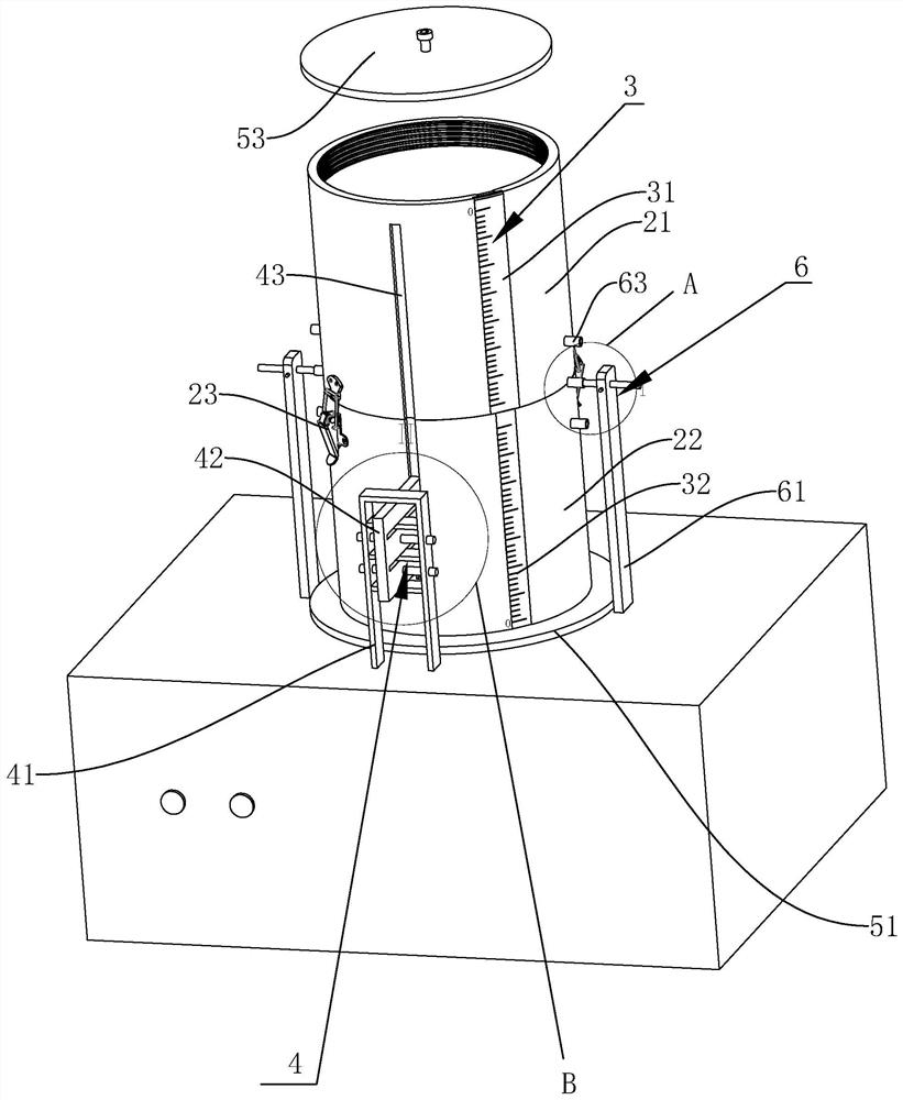
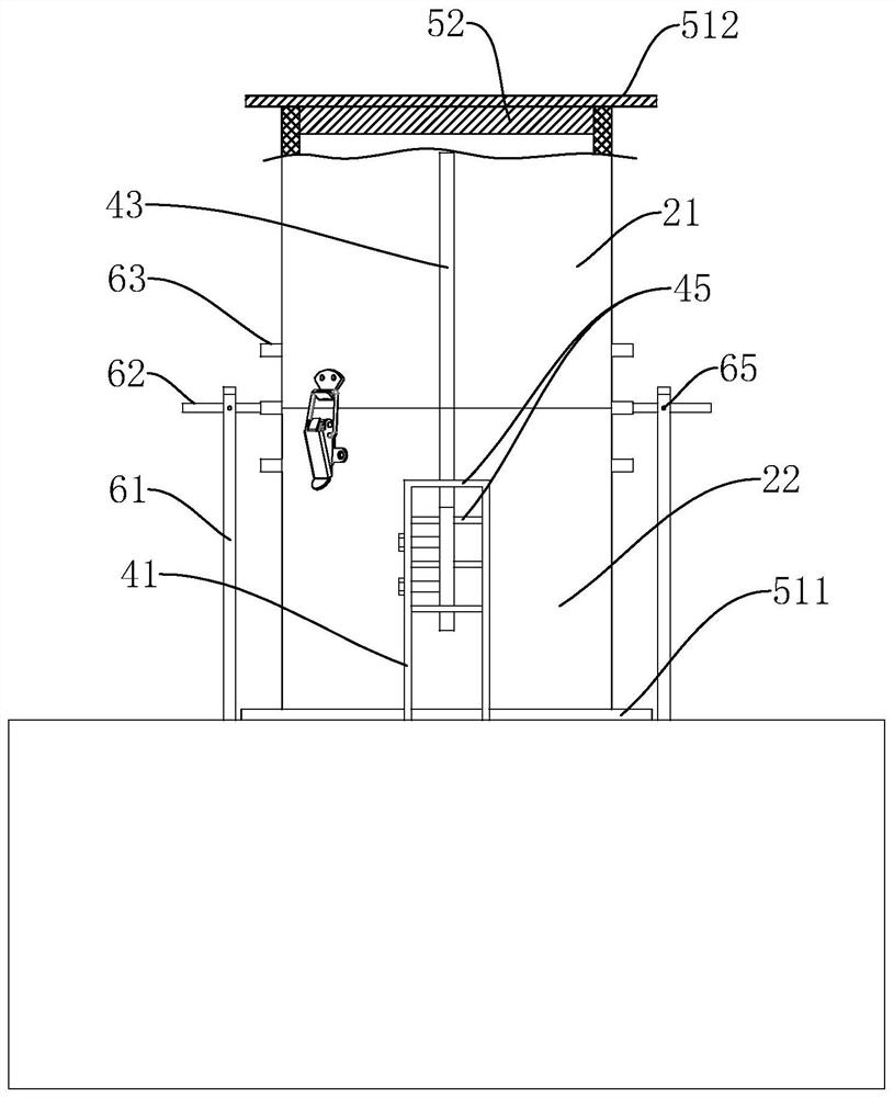
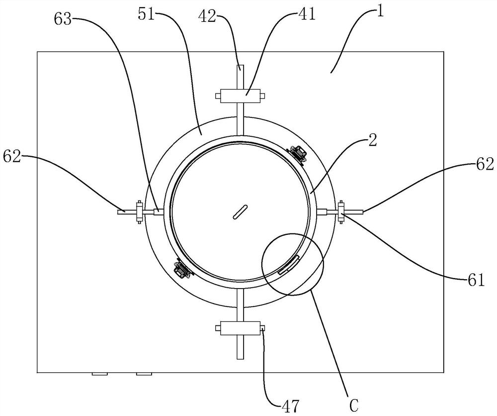
[0053] Such as figure 1 As shown, the application provides a vibrating table 1 method experimental device for soil dry density testing, including a vibrating table 1, a vibrating cylinder 2, a transparent measuring mechanism 3 for viewing and measuring the soil volume in the vibrating cylinder 2 in real time, capable of The turning mechanism 6 that allows the vibrating cylinder 2 to turn 180° on the vibrating table 1, and the lifting and lowering mechanism 4 for making the vibrating cylinder 2 can only move vertically on the vibrating table 1. The vibrating cylinder 2 includes a sleeve 21 and the test cylinder 22 , a cylinder fastener 23 connecting the sleeve 21 and the test cylinder 22 is connected between the sleeve 21 and the test cylinder 22 .

[0054] During actual work, this application is mainly aimed at the existing "vibrating table 1 method" experim...


PUM


Abstract

The invention relates to a vibration table method experimental device for testing the dry density of soil, and an experimental method thereof, and relates to the technical field of geotechnical engineering measurement. The device comprises a vibration table, a vibration cylinder, a transparent measuring mechanism and a lifting limiting mechanism; the lower end of the vibration cylinder is connected with a base, a supporting disc is installed on the base, and a compaction disc is placed in the vibration cylinder; the lifting limiting mechanism comprises a lifting limiting support and a liftinglimiting plate; and a first limiting groove is formed in the outer wall of the vibration cylinder, one end of the lifting limiting plate corresponds to the first limiting groove in position, the otherend of the lifting limiting plate is slidably placed on the lifting limiting support, a plate limiting assembly is further arranged between the lifting limiting plate and the lifting limiting support, and a cylinder limiting assembly is further connected between the lifting limiting support and the vibration table. The total volume test result error of the soil is small, and the soil dry densitycalculation result error is small.

Description

technical field [0001] The invention relates to the technical field of geotechnical engineering measurement, in particular to a shaking table method experimental device and an experimental method for soil dry density testing. Background technique [0002] Dry density refers to the density when there is no water in the pores of the soil, that is, the ratio of the mass of solid particles to the total volume of the soil. The dry density reflects the void ratio of the soil, so it can be used to calculate the porosity of the soil. It is often calculated from the density and moisture content of the soil. The specific method is as follows: first calculate the wet density of the soil, and then divide it by (1+w) , that is, the dry density of the soil is calculated according to the formula ρd=ρ / (1+w), wherein ρd is the dry density of the soil, ρ is the wet density of the soil, and w is the water content of the soil. [0003] According to the Ministry of Housing and Urban-Rural Devel...

Claims


Application Information

Patent Timeline
Patent Type & Authority Applications(China)
IPC IPC(8): G01N1/28G01N9/00
CPCG01N1/286G01N9/00
Inventor 付亚军胡登鹏谭小平马豪远杜书圣
Owner 湖北瑞鹏恒信检测有限公司
Why Eureka
Try Eureka