Equipment for preparing carbon ceramic through graphite powder

A technology of graphite powder and carbon ceramics, applied in the field of carbon ceramics, can solve the problems of low production efficiency, inability to realize carbon ceramics molding and output continuity, etc. Effect

Active Publication Date: 2021-02-12
SINOSTEEL NEW MATERIAL ZHEJIANG
View PDF7 Cites 1 Cited by
  • Summary
  • Abstract
  • Description
  • Claims
  • Application Information

AI Technical Summary

Problems solved by technology

[0005] The purpose of the present invention is to address the deficiencies of the prior art. By setting the forming mechanism to cooperate with the feeding mechanism and the output mechanism, the forming mechanism can sequentially complete the uniform and quantitative feeding and forming work of the graphite powder by the feeding mechanism during the transmission process. And the downward output work of the output mechanism to the carbon ceramics, thus solving the technical problems that the carbon ceramics cannot be formed and output continuity, and the production efficiency is low in the pressing and forming work

Method used


Image

  • Equipment for preparing carbon ceramic through graphite powder
  • Equipment for preparing carbon ceramic through graphite powder
  • Equipment for preparing carbon ceramic through graphite powder

Examples


Embodiment 1

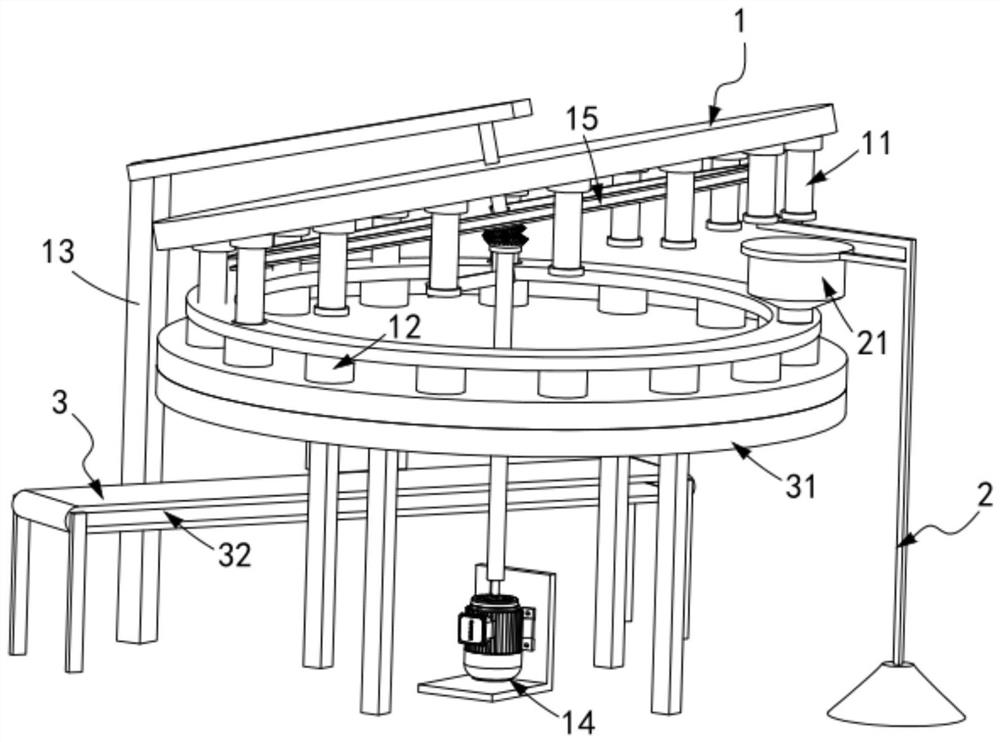
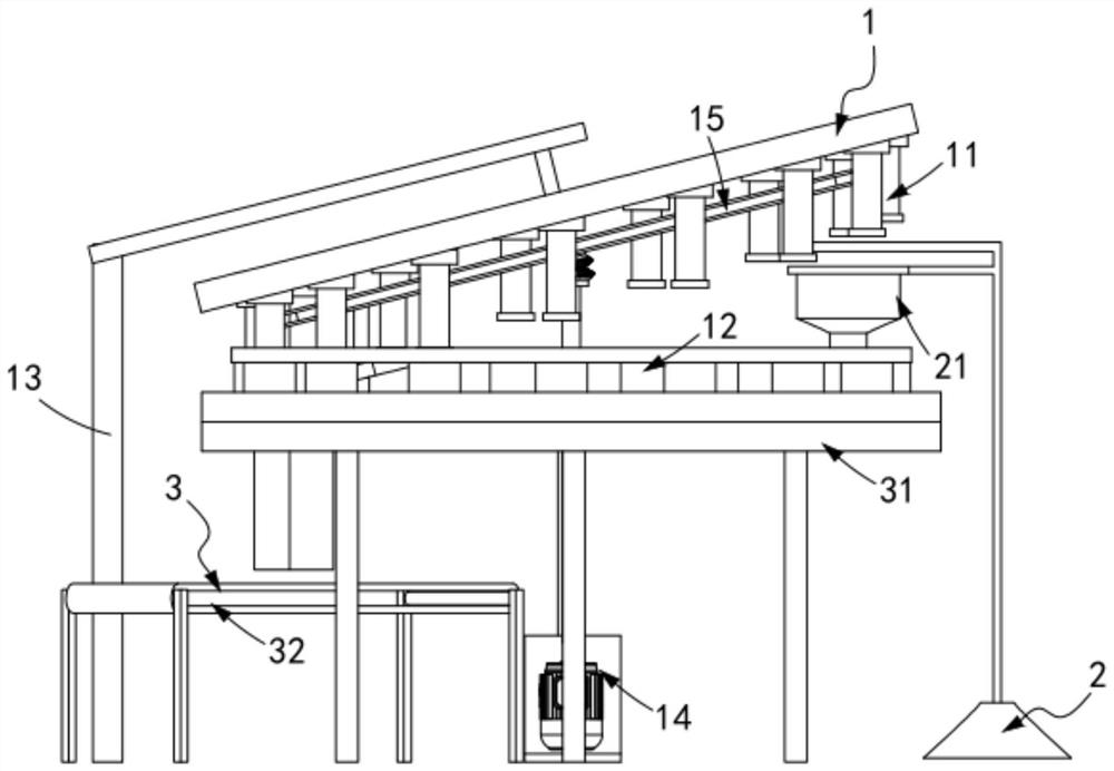
[0050] Such as figure 1 , figure 2 Shown, a kind of equipment that utilizes graphite powder to prepare carbon pottery, comprises:

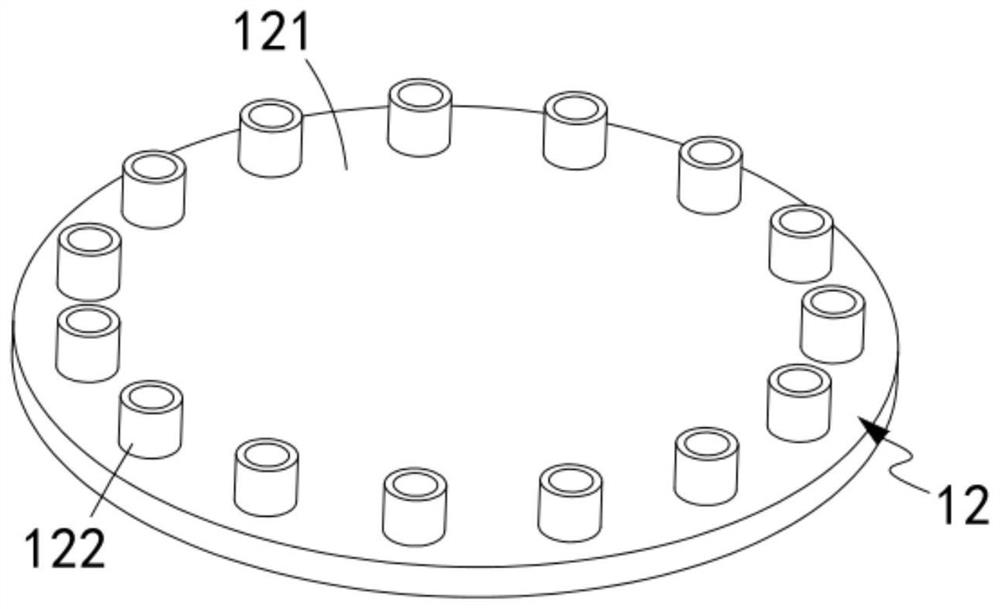
[0051]Forming mechanism 1, described forming mechanism 1 comprises upper mold assembly 11, lower mold assembly 12, is used to drive described upper mold assembly 11 and lower mold assembly 12 to rotate synchronously and is installed on the driving assembly 14 on frame 13 and is installed on The first guide assembly 15 on the frame 13 and used to guide the upper mold assembly 11 to rotate in parallel along the circumferential surface of the upper mold assembly 11, the lower mold assembly 12 is sequentially provided with Loading station Ⅰ, forming station Ⅱ and output station Ⅲ;

[0052] A feeding mechanism 2, the feeding mechanism 2 includes a material storage assembly 21 arranged on the frame 13, the feeding mechanism 2 is located on the feeding station I; and

[0053] The output mechanism 3, the output mechanism 3 includes a discharge assembl...

Embodiment 2

[0075] Such as Figure 13 As shown, the components that are the same as or corresponding to those in the first embodiment are marked with the corresponding reference numerals in the first embodiment. For the sake of simplicity, only the differences from the first embodiment will be described below. The difference between this embodiment two and embodiment one is:

[0076] further, such as Figure 13 As shown, the transmission assembly 32 is a belt pulley transmission mode;

[0077] The distance between the lower surface of the temporary storage box 312 and the upper surface of the conveying assembly 32 is equal to the thickness of the carbon ceramic 10 .

[0078] It is worth mentioning here that by setting the temporary storage box 312, the height of the carbon ceramics falling output is shortened, thereby reducing the degree of collision wear of the carbon ceramics output and improving product quality; it should be noted that the inner wall of the temporary storage box 312 ...


PUM


Abstract

The invention relates to equipment for preparing carbon ceramic through graphite powder. The equipment comprises a forming mechanism, a feeding mechanism and an output mechanism. The forming mechanismcomprises an upper die assembly, a lower die assembly, a driving assembly and a first guide assembly, and the lower die assembly is sequentially provided with a feeding station, a forming station andan output station in the circumferential rotation direction. The feeding mechanism comprises a storage assembly arranged on a rack, and the feeding mechanism is located on the feeding station. The output mechanism comprises a discharging assembly arranged below the lower die assembly, a conveying assembly arranged below the discharging assembly and a second guide assembly used for driving the upper die assembly to automatically output carbon ceramic in the lower die assembly to the discharging assembly, the first guide assembly is in smooth transition connection with the second guide assembly, and the output mechanism is located at the output station. The equipment solves the technical problems that in the pressing forming work, carbon ceramic forming and output continuity cannot be achieved, and the production efficiency is low.

Description

technical field [0001] The invention relates to the technical field of carbon ceramics, in particular to a device for preparing carbon ceramics from graphite powder. Background technique [0002] In practical applications, high-strength, high-hardness, and high-corrosion-resistant carbon graphite materials will not appear at the same time. If you want to make carbon graphite materials that can cope with these three high performances at the same time, the process is difficult, the production cycle is long, and the cost is too high. It is not suitable for mass promotion and application in the market. Because carbon powder and carbon fiber are still pure carbon graphite materials, they are soft in nature. It is difficult to bear the particles that exceed its hardness during frictional movement, which will cause accelerated wear and short life. Therefore, the carbon material itself is Difficult to cope with this situation. [0003] The patent document whose patent number is CN...

Claims


Application Information

Patent Timeline
Patent Type & Authority Applications(China)
IPC IPC(8): B30B11/06B30B15/30B30B15/32
CPCB30B11/06B30B15/302B30B15/32
Inventor 马伟冯国超
Owner SINOSTEEL NEW MATERIAL ZHEJIANG
Why Eureka
Try Eureka