
Device for producing high-quality building materials

A kind of building material, high-quality technology, applied in the field of cement processing, can solve the problems of unbalanced force on the device, uneven distribution, large wear noise, etc., to achieve the effect of avoiding rotation, enhancing anti-interference, and reducing distance

Inactive Publication Date: 2021-02-12
杭州雷力信息科技有限公司
View PDF8 Cites 6 Cited by
  • Summary
  • Abstract
  • Description
  • Claims
  • Application Information

AI Technical Summary

Problems solved by technology

[0002] Cement rotary kiln is one of the most important equipment in the process of changing raw material into clinker in cement processing. The existing cement rotary kiln is generally relatively large in size. , the entire device is installed at an angle of 1-3°, and relies on gravity to complete the feeding work, but such a cement rotary kiln has already had major disadvantages. First, it is difficult to install such a large-scale equipment at an angle, due to the uneven force on the entire device Second, due to the high temperature, the refractory brick lining the kiln is often burned through and needs to be replaced, but the replacement position is random, and the kiln body formed by integral welding is not easy to replace, and the entire device needs to be shut down Enter a longer kiln body for replacement; third, relying on gravity feeding often makes the distribution of raw materials in the kiln body uneven, adding unnecessary load to the kiln body, and raw materials are heated unevenly throughout the process, resulting in poor product quality

Method used


Image

  • Device for producing high-quality building materials
  • Device for producing high-quality building materials
  • Device for producing high-quality building materials

Examples


Embodiment Construction

[0023] In order to enable those in the technical field to better understand the solutions of the present invention, the technical solutions in the embodiments of the present invention will be clearly and completely described below in conjunction with the drawings in the embodiments of the present invention.

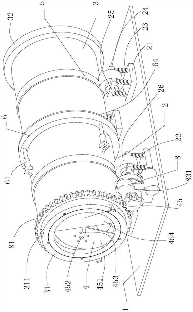
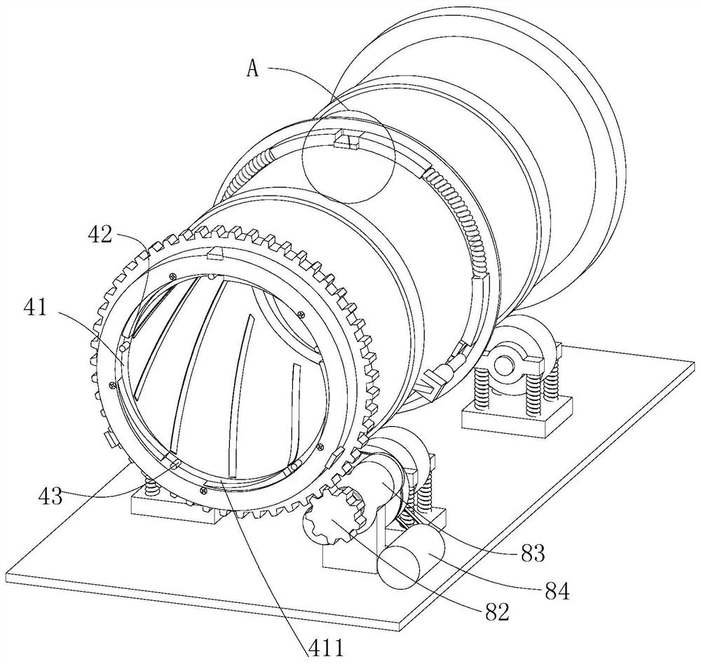
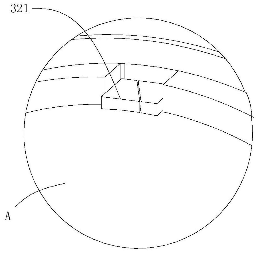
[0024] Such as Figure 1-9As shown, a device for producing high-quality building materials includes a mounting base 1, a support wheel assembly 2, a rotary kiln body 3, a kiln head 31, a sub-wedge 311, a feeding mechanism 4, a wheel belt 5, a splicing buckle 6, a hydraulic Rod 61, kiln tail 32, female wedge 321, sealing assembly 7 and pulse drive mechanism 8; the support wheel assembly 2 is fixedly installed on the installation base 1; the rotary kiln body 3 is located on the installation base 1 above; the kiln head 31 of the rotary kiln body 3 of the sub-wedge 311; the feeding mechanism 4 is located at the kiln head 31 and is rotatably connected with the kiln head 31; th...


PUM


Abstract

The invention discloses a device for producing high-quality building materials. The device comprises a mounting base, a riding wheel assembly fixedly mounted on the mounting base and a rotary kiln body located on the mounting base; and the rotary kiln body comprises a kiln head provided with a child wedge block, a feeding mechanism arranged on the kiln head, a wheel belt fixedly connected to the surface of the rotary kiln body, a splicing buckle located on the rear side of the wheel belt, a hydraulic rod used for driving the splicing buckle, a kiln tail provided with a mother wedge block, a sealing assembly arranged at the end part of the kiln tail, and a driving mechanism used for driving the rotary kiln body. According to the device, splicing and fixing of a rotary cement kiln are achieved through the child wedge block, the mother wedge block and the splicing buckle at the kiln opening and the kiln tail, torque can be well transmitted, and meanwhile dismounting, repairing and maintaining are more convenient; a horizontal feeding mechanism is arranged, so that under the condition that the device has no preset inclination angle, normal operation of calcination can be guaranteed, and effective feeding work can also be carried out; and therefore, the problem that the rotary cement kiln must be obliquely mounted for a long time is solved.

Description

technical field [0001] The invention belongs to the technical field of cement processing, and in particular relates to a device for producing high-quality building materials. Background technique [0002] Cement rotary kiln is one of the most important equipment in the process of changing from raw material to clinker in cement processing. The existing cement rotary kiln is generally relatively large in size. , the entire device is installed at an angle of 1-3°, and relies on gravity to complete the feeding work, but such a cement rotary kiln has already had major disadvantages. First, it is difficult to install such a large-scale equipment at an angle, due to the uneven force on the entire device Second, due to the high temperature, the refractory bricks lining the kiln are often burned through and need to be replaced, but the replacement position is random, and the integrally welded kiln body is not easy to replace, requiring the entire device to be shut down Enter a longe...

Claims


Application Information

Patent Timeline
Patent Type & Authority Applications(China)
IPC IPC(8): B65D88/74B65D90/12
CPCB65D88/744B65D90/12
Inventor 陈琳玲
Owner 杭州雷力信息科技有限公司
Learn More