
Method for reducing flow resistance of interlayer cooling structure of 3D printing thrust chamber

A cooling structure and 3D printing technology, applied in the field of 3D printing, can solve problems such as interlayer channel flow resistance, achieve the effects of reducing flow resistance, improving flow resistance efficiency, and reducing surface roughness

Inactive Publication Date: 2021-02-12
XIAN UNIV OF TECH +1
View PDF11 Cites 4 Cited by
  • Summary
  • Abstract
  • Description
  • Claims
  • Application Information

AI Technical Summary

Problems solved by technology

[0007] The purpose of the present invention is to provide a method for reducing the flow resistance of the interlayer cooling structure of the 3D printing thrust chamber, so as to solve the problem of the flow resistance of the interlayer channel during the liquid flow test

Method used


Image

  • Method for reducing flow resistance of interlayer cooling structure of 3D printing thrust chamber
  • Method for reducing flow resistance of interlayer cooling structure of 3D printing thrust chamber
  • Method for reducing flow resistance of interlayer cooling structure of 3D printing thrust chamber

Examples


Embodiment Construction

[0026] The present invention will be described in detail below in conjunction with the accompanying drawings and specific embodiments.

[0027] The present invention provides a method for reducing the flow resistance of the interlayer cooling structure of the 3D printing thrust chamber, which is specifically implemented according to the following steps:

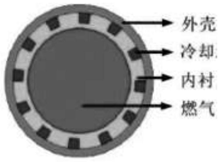
[0028] Step 1. First, construct and design the interlayer cooling structure of the thrust chamber. The interlayer structure includes an inner layer and an outer layer. The coolant inlet and outlet should be set at both ends. The middle of the interlayer structure is divided into multiple cooling channels by several axial ribs. , including the inflow channel and the outflow channel, the two channels should be arranged adjacent to each other in turn, and a plurality of lattice protrusions should be arranged at intervals in the circulation channel to further improve the cooling capacity of the interlayer. Then use Solidworks sof...


PUM


Abstract

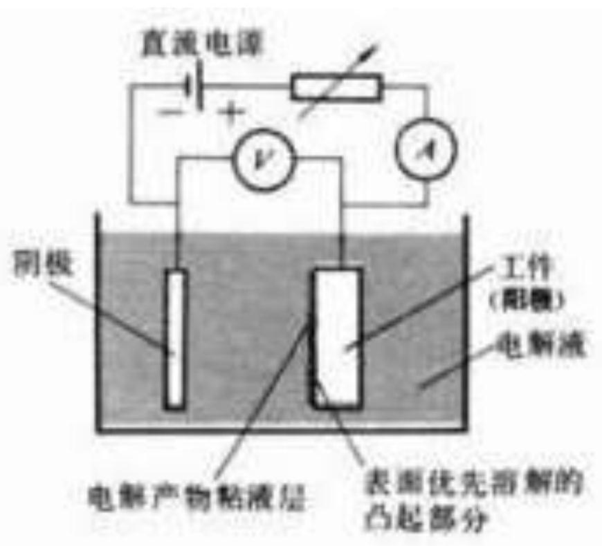
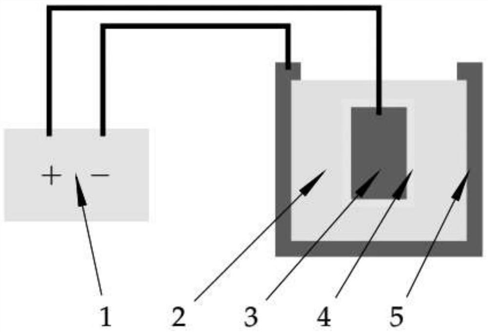
The invention discloses a method for reducing the flow resistance of an interlayer cooling structure of a 3D printing thrust chamber. The method comprises the following steps: firstly, the interlayercooling structure of the thrust chamber is optimally designed, and then a workpiece is formed by adopting a 3D printing technology; the formed interlayer cooling structure of the thrust chamber is treated by adopting an electrochemical polishing and plasma electrolytic polishing technology; and through cooperation of the two technologies, the needed workpiece can further reach the needed performance, rough polishing is conducted through the electrochemical polishing technology, and fine polishing is conducted through the plasma electrolytic polishing technology. According to the plasma electrolytic polishing technology, the surface quality of parts can be improved by adjusting the proportion of electrolyte and the magnitude of current and voltage, initiation and expansion of a crack sourceare effectively reduced, the flow resistance of the interlayer cooling structure of the thrust chamber is effectively reduced, the service condition of the interlayer cooling structure of the thrustchamber under specific conditions is achieved, the problem of workpieces at present is solved, and the application range of the 3D printing technology and a surface modification technology in the aerospace field is widened.

Description

technical field [0001] The invention belongs to the field of 3D printing technology, and in particular relates to a method for reducing the flow resistance of an interlayer cooling structure of a 3D printing thrust chamber. Background technique [0002] The thrust chamber is an important component that converts the chemical energy of the liquid propellant into propulsion, and plays an extremely important role in the engine. It will be eroded by corrosive high-temperature and high-pressure gas during operation. In order to effectively export heat and perform normally, the design of the thrust chamber and the selection of materials are particularly important. The traditional thrust chamber interlayer cooling structure has complicated manufacturing process, long manufacturing cycle and different quality levels. The use of 3D printing technology to form the interlayer cooling structure of the thrust chamber can meet the requirements of complex design, low cost and fast delivery...

Claims


Application Information

Patent Timeline
Patent Type & Authority Applications(China)
IPC IPC(8): C25F3/16B22F10/60B33Y40/20
CPCC25F3/16B22F3/24B33Y40/20B22F2003/247
Inventor 杨鑫孙晨皞范亚卓苗庆东赵三超谢波
Owner XIAN UNIV OF TECH
Learn More