Combined non-metal sound barrier unit plate

A non-metal, sound barrier technology, used in construction, noise absorption devices, etc., can solve the problems of easy aging of sound absorbing materials, poor resonance and noise reduction effect, and inability to adjust, and achieve good ramming effect, sound absorption and sound insulation. Excellent performance and easy installation and construction

Pending Publication Date: 2021-02-12
衡水中裕铁信环保工程有限公司
View PDF1 Cites 2 Cited by
  • Summary
  • Abstract
  • Description
  • Claims
  • Application Information

AI Technical Summary

Problems solved by technology

Although the metal sound barrier has the advantages of easy installation, easy maintenance, and easy scale manufacturing, it has obvious disadvantages such as poor coordination with the landscape, easy aging of sound-absorbing materials, poor corrosion resistance, and low fatigue strength.
Non-metallic sound barriers have the advantages of corrosion resistance, no pollution, and low cost, but most of them have heavy weight, insufficient strength, low sound absorption performance, and relatively simple structural forms and materials. The shortcomings of sound-absorbing materials, such as easy failure, short effective life, and troublesome maintenance and replacement, increase the cost of using sound barriers, resulting in poor economic and social benefits
[0005] The utility model with the patent No. CN206538699U discloses a non-metallic sound barrier for high-speed railways. The sound barrier includes a concrete shell formed by one-time pouring. The large cavity part is close to the shell panel and filled with sound-absorbing body. The steps in the cavity form the positioning boss of the sound-absorbing body, thereby adjusting the higher sound absorption coefficient of the sound barrier. However, This improvement is simple in structure and single in form, and its synergistic resonance effect with sound-absorbing materials is poor, and it cannot be adjusted according to the noise source.

Method used


Image

  • Combined non-metal sound barrier unit plate
  • Combined non-metal sound barrier unit plate

Examples


Embodiment Construction

[0022] The structure and working principle of a combined non-metallic sound barrier unit panel provided by the present invention will be further described in detail below with reference to the accompanying drawings.

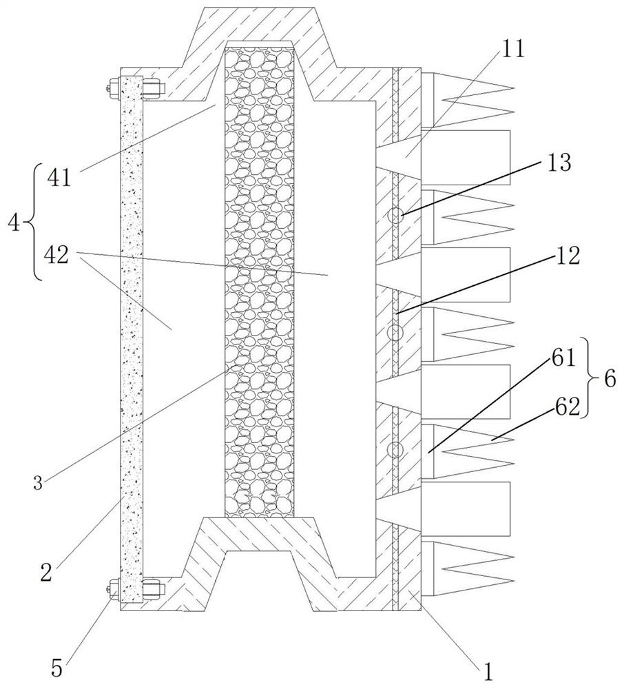
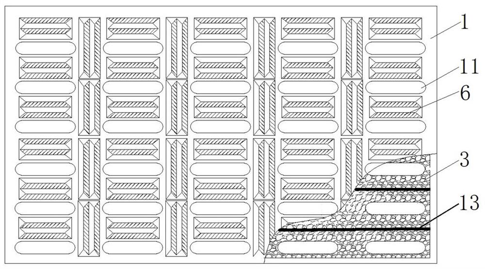
[0023] see figure 1 , is a schematic cross-sectional view of a combined non-metallic sound barrier unit panel provided by the present invention. The structure constituting the combined non-metallic sound barrier unit panel includes a panel 1, a back panel 2 and a sound-absorbing material 3 placed between them; wherein, the panel 1 is recessed to form a shell with a cavity 4, and the sound-absorbing material 3 Placed in the box cavity 4, the panel 1 and the back panel 2 are connected 5 by bolts, the panel 1 is poured from air-filled concrete, and the panel 1 is provided with evenly distributed sound-absorbing holes 11 .

[0024] Its working principle is: the panel 1 of the combined non-metallic sound barrier unit panel is formed by pouring air bubble concrete, sp...


PUM


Abstract

The invention belongs to the technical field of non-metal sound barriers, and particularly relates to a combined non-metal sound barrier unit plate. Wherein the sound absorption plate comprises a panel, a back plate and a sound absorption material arranged between the panel and the back plate; wherein the panel is concaved inwards to form an outer shell with a box cavity, the sound absorption material is arranged in the box cavity, the panel and the back plate are connected through bolts, the panel is formed by pouring bubble concrete, and sound absorption holes are evenly distributed in the panel. The combined type nonmetal sound barrier unit plate has the advantages of being light in weight, high in durability, low in use cost and convenient to assemble and disassemble, and various soundabsorption structures achieve cooperative noise elimination.

Description

technical field [0001] The invention belongs to the technical field of non-metallic sound barriers, and in particular relates to a combined non-metallic sound barrier unit plate. Background technique [0002] The sound barrier is set on the wall structure next to the railway and road to reduce the impact of driving noise on nearby residents. By inserting a barrier facility between the noise source and the receiver, the sound wave propagation has a significant additional attenuation, thereby reducing the impact of noise in a certain area where the receiver is located. [0003] In recent years, with the in-depth advancement of my country's transportation industry, especially the rapid development of high-speed railway construction, the noise problem along the line has become one of the serious pollution affecting people's quality of life. Therefore, the construction of sound barriers is the most effective way to solve the noise nuisance of high-speed rail. [0004] The exist...

Claims


Application Information

Patent Timeline
Patent Type & Authority Applications(China)
IPC IPC(8): E01F8/00
CPCE01F8/00E01F8/0023E01F8/0029
Inventor 郭勇郑永春刘学斌栾旭猛侯若敬张丽珍张朝阳杨鹏展
Owner 衡水中裕铁信环保工程有限公司
Why Eureka
Try Eureka