Shock-resistant high-sensitivity induction detection sensor measuring device

A high-sensitivity, inductive detection technology, applied in the direction of measuring devices, testing/calibrating devices, measuring capacity, etc., can solve problems such as unstoppable sensors, affecting measurement accuracy, and probe rod breakage, achieving high measurement accuracy and low signal-to-noise Good ratio, the effect of reducing the contact area

Active Publication Date: 2021-02-19
姚宁
View PDF14 Cites 0 Cited by
  • Summary
  • Abstract
  • Description
  • Claims
  • Application Information

AI Technical Summary

Problems solved by technology

[0006] The structure of the above-mentioned flowmeter also has the following common problems: (1) It is easy to transfer the vibration interference of the pipeline that transports the flow to the detection sensor (or probe); (2) Both use a signal vibration rod or a vortex generator. Longer and heavier, the mass of the vortex is larger, which is easy to cause self-shock interference or resonance interference; (3) Most of the probes use a flange mounting structure, and a gasket is used between it and the meter body, which sometimes occurs In case of leakage accidents, the sensor cannot be replaced online without stopping; (4) The vibrating rod of the probe of the above-mentioned flowmeter generally penetrates into the inner diameter of the pipeline surface and is behind the tail of the vortex generating body. , so this structure will produce nonlinear distortion and affect the measurement accuracy, which is an insurmountable problem for vortex flowmeters. A certain oscillation frequency will break the probe rod

Method used


Image

  • Shock-resistant high-sensitivity induction detection sensor measuring device
  • Shock-resistant high-sensitivity induction detection sensor measuring device
  • Shock-resistant high-sensitivity induction detection sensor measuring device

Examples


Embodiment 1

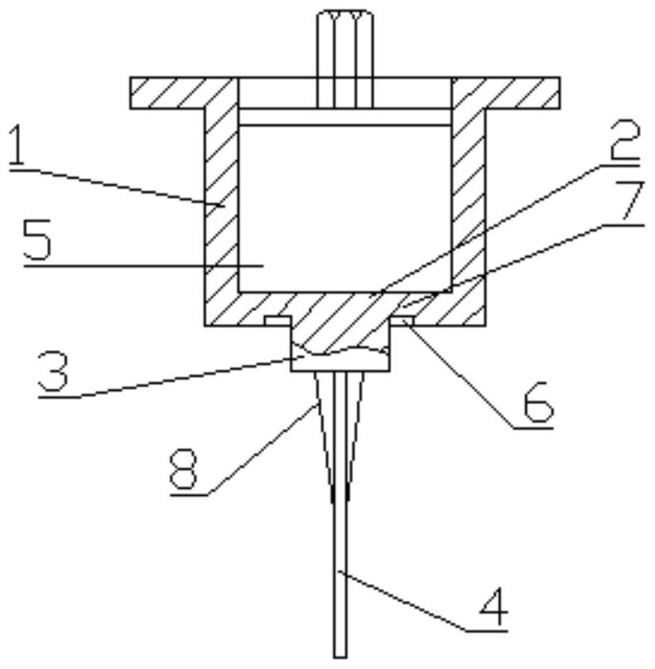
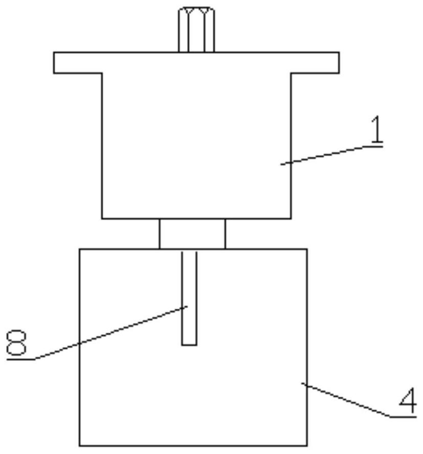
[0027] Such as figure 1 with figure 2In the shown embodiment, an anti-seismic high-sensitivity induction detection sensor measuring device includes a measuring cavity 1, and the measuring cavity 1 is a welded threaded measuring cavity, or a flanged threaded measuring cavity; the measuring cavity The lower end of the body 1 is provided with a shock-sensing sheet 2, the lower end of the shock-sensing sheet 2 is provided with a cylinder 3, the lower end of the cylinder 3 is provided with a shock-absorbing signal vibration mechanism 4, and the inside of the measuring cavity 1 is provided with a detection sensor 5, The lower end surface of the vibration-sensing sheet 2 is provided with an annular groove 6 and an annular sheet 7 , and the detection sensor 5 is arranged on the upper end surface of the vibration-sensing sheet 2 by packaging or pressing with a fastener.

[0028] In this embodiment, the earthquake-resistant high-sensitivity induction detection sensor measuring device ...

Embodiment 2

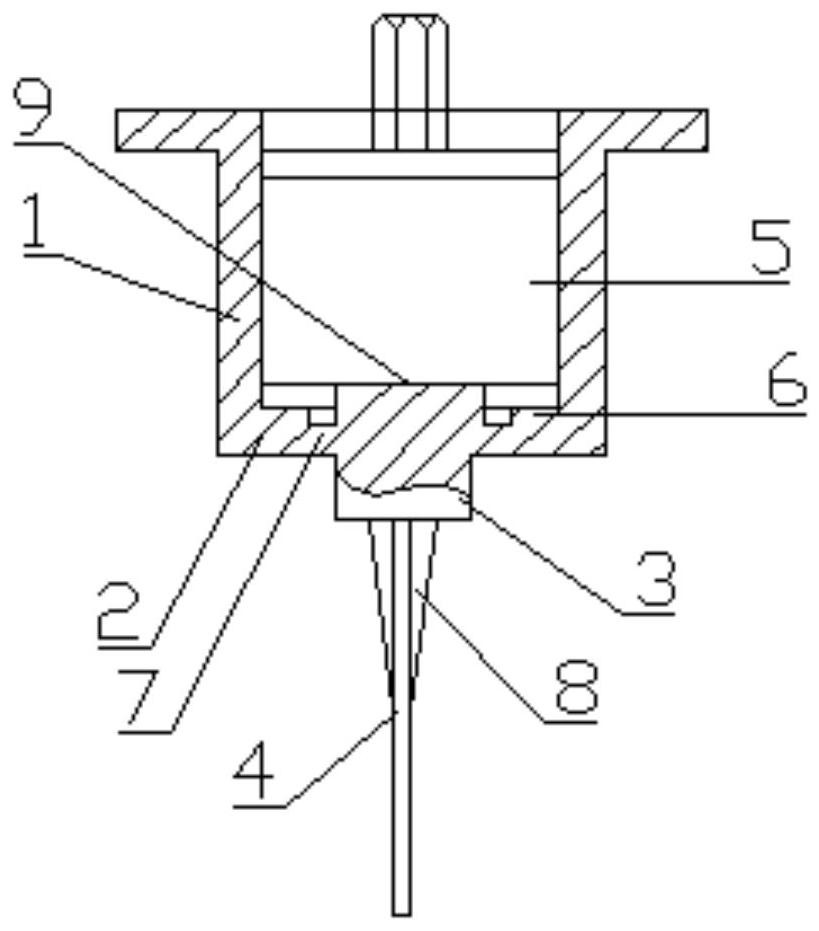
[0034] Such as image 3 In the shown embodiment, an anti-seismic high-sensitivity induction detection sensor measuring device includes a measuring cavity 1, and the measuring cavity 1 is a welded threaded measuring cavity, or a flanged threaded measuring cavity; the measuring cavity The lower end of the body 1 is provided with a shock-sensing sheet 2, the lower end of the shock-sensing sheet 2 is provided with a cylinder 3, the lower end of the cylinder 3 is provided with a shock-absorbing signal vibration mechanism 4, and the inside of the measuring cavity 1 is provided with a detection sensor 5, The upper end surface of the shock-sensing sheet 2 is provided with an annular groove 6 and an annular sheet 7, the upper end of the shock-sensing sheet 2 is provided with an upper cylinder 9, and the detection sensor 5 is arranged on the upper cylinder by packaging or tightening with fasteners. 9 on the end face.

[0035] In this embodiment, the earthquake-resistant high-sensitivit...


PUM


Abstract

The invention relates to the technical field of detection sensor measuring devices, in particular to a shock-resistant high-sensitivity induction detection sensor measuring device. The shock-resistanthigh-sensitivity induction detection sensor measuring device comprises a measuring cavity, a shock sensing piece is arranged at the lower end of the measuring cavity, a column body is arranged at thelower end of the shock sensing piece, a damping signal vibration mechanism is arranged at the lower end of the column body, and a detection sensor is arranged in the measuring cavity. An annular groove and an annular sheet are arranged on the upper end face or / and the lower end face of the shock sensing piece, the damping signal vibration mechanism is a damping signal vibration sheet, and a shockabsorption structure is arranged on the damping signal vibration sheet. The shock-resistant high-sensitivity induction detection sensor measuring device provided by the invention not only meets the requirement of sensitivity, but also meets the requirement of pressure resistance, and reduces the contact area between the detection sensor and the shock sensing piece, thereby reducing the shock interference or signal noise.

Description

technical field [0001] The invention relates to the technical field of detection sensor measurement devices, in particular to an anti-seismic high-sensitivity induction detection sensor measurement device. Background technique [0002] The birth of the first vortex flowmeter in the 1970s caused a sensation in the world's flow industry. American experts predicted that it would replace the throttling devices that have been widely used for hundreds of years in the near future. For decades, scientists from all over the world, scientific and technical personnel in the flow industry, and users have made unremitting efforts in scientific research, production, and application, and vortex streets for thermistors, piezoelectric crystals, differential capacitors, ultrasonic waves, and other principles and device manufacturing have appeared one after another. Flowmeter, because its core component is the vortex flow sensor (or signal detector, probe, sensor head) that detects the flow si...

Claims


Application Information

Patent Timeline
Patent Type & Authority Applications(China)
IPC IPC(8): G01F25/00G01F1/32G01F15/00
CPCG01F1/32G01F15/00G01F25/10
Inventor 姚贤卿迟军科薛成钢柴宏波郜斌吕泽锋林夕庆王晓东姚宁吕长达陈方霞付菲菲任连涛王俊河赵宏志
Owner 姚宁
Why Eureka
Try Eureka