Cascade circuit based on gate protection and cascade device
A technology for cascading circuits and devices, applied in the direction of electric solid devices, circuits, electrical components, etc., can solve the problems of unapplied power devices and insufficient driving ability, and achieve practical value, reduce equivalent Miller capacitance, reduce The effect of the effect of switching speed
- Summary
- Abstract
- Description
- Claims
- Application Information
AI Technical Summary
Problems solved by technology
Method used
Image
Examples
Embodiment 1
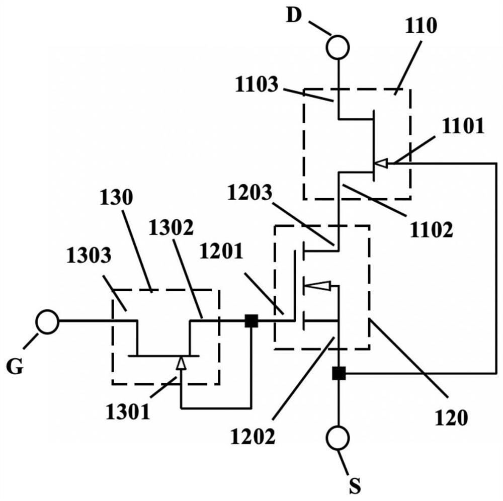
[0039] ginseng figure 1 As shown, a cascade circuit is disclosed in this embodiment, and the cascade circuit includes:
[0040] A high-voltage depletion device 110, a low-voltage enhancement device 120, and a low-voltage depletion device 130. The high-voltage depletion device 110 includes a first gate 1101, a first source 1102, and a first drain 1103. The low-voltage enhancement device 120 Including a second gate 1201 , a second source 1202 and a second drain 1203 , the low voltage depletion device 130 includes a third gate 1301 , a third source 1302 and a third drain 1303 . Wherein, the first source 1102 is electrically connected to the second drain 1203, the first gate 1101 is electrically connected to the second source 1202, and the second gate 1201 is electrically connected to the third source 1302 and the third gate 1301. The first drain 1103 serves as the drain D of the cascode circuit, the second source 1202 serves as the source S of the cascade circuit, and the third ...
Embodiment 2
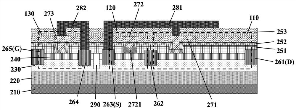
[0046] ginseng figure 2 As shown, a cascaded device is disclosed in this embodiment, and the cascaded device mainly includes a high voltage depletion device 110 , a low voltage enhanced device 120 and a low voltage depletion device 130 .
[0047] Specifically, the cascode device includes a substrate 210 , an epitaxial structure on the substrate, several passivation layers and several electrodes on the epitaxial structure.
[0048] Wherein, the epitaxial structure includes a channel layer 230 located on the substrate 210 and a barrier layer 240 located on the channel layer 230. Preferably, the epitaxial structure in this embodiment further includes a layer located between the channel layer 230 and the substrate 210. The buffer layer 220 between them.
[0049] Specifically, substrate 210 is one of silicon, sapphire, silicon carbide, etc.; buffer layer 220 is a combination of one or more of aluminum nitride layer, gallium nitride layer, aluminum gallium nitride layer, etc.; the...
Embodiment 3
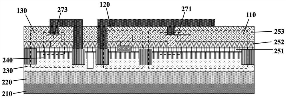
[0068] ginseng image 3 As shown, the cascaded device in this embodiment is similar to the cascaded structure in Embodiment 2, except for the high-voltage depletion device 110 and the low-voltage depletion device 130 .
[0069] In the high-voltage depletion-mode device 110 of this embodiment, the first gate 271 realizes the depletion-mode operation mode by a metal-insulator-semiconductor-based structure, and the first depletion region includes the entire second passivation layer 252 The first groove (not shown), the first grid 271 is partly located in the first groove, the first dielectric layer 251 is formed between the first grid 271 and the barrier layer 240, and the first dielectric layer 251 is used as a metal - insulating layer - an insulating layer in the structure of a semiconductor.
[0070] In the low-voltage depletion device 130 of this embodiment, the third gate 273 realizes the depletion mode of operation by a structure based on a metal-insulator-semiconductor, a...
PUM
| Property | Measurement | Unit |
|---|---|---|
| thickness | aaaaa | aaaaa |
| thickness | aaaaa | aaaaa |
| porosity | aaaaa | aaaaa |
Abstract
Description
Claims
Application Information
 - R&D
- Intellectual Property
- Life Sciences
- Materials
- Tech Scout
- Unparalleled Data Quality
- Higher Quality Content
- 60% Fewer Hallucinations
Browse by: Latest US Patents, China's latest patents, Technical Efficacy Thesaurus, Application Domain, Technology Topic, Popular Technical Reports.
© 2025 PatSnap. All rights reserved.Legal|Privacy policy|Modern Slavery Act Transparency Statement|Sitemap|About US| Contact US: help@patsnap.com


