Motor iron core winding equipment

A technology of iron core and equipment, applied in the field of iron core manufacturing, can solve the problems of difficult to guarantee the yield rate of the winding process, waste of material scraps, low utilization rate of materials, etc., achieving dimensional stability, continuous and automatic winding process, and utilization of raw materials. high rate effect

Pending Publication Date: 2021-02-19
张莉
View PDF0 Cites 0 Cited by
  • Summary
  • Abstract
  • Description
  • Claims
  • Application Information

AI Technical Summary

Problems solved by technology

[0003] In traditional iron core processing, the shape of iron chips is punched out on the plate, and then stacked together and welded together. The material utilization rate of this method is very low, and a large amount of material is wasted as scrap;
[0004] In the existing technology, more and more iron cores are manufactured by coiling process. The raw material is the steel strip coil on which the embedding groove has been punched. According to the different specifications, types and forms of the motor, the cross-sectional shape of the iron core is different. Therefore, pre-stamped steel coils are not universal, and in the prior art, direct cold bending, the bending stress accumulates in the iron core, and its tendency is to open outwards, although the size will be eliminated through finishing, stress relief and other processes However, the larger bending stress directly affects the winding process, resulting in larger dimensional deviations, and the yield rate of the winding process is difficult to guarantee

Method used


Image

  • Motor iron core winding equipment
  • Motor iron core winding equipment
  • Motor iron core winding equipment

Examples


Embodiment Construction

[0023] The following will clearly and completely describe the technical solutions in the embodiments of the present invention with reference to the accompanying drawings in the embodiments of the present invention. Obviously, the described embodiments are only some, not all, embodiments of the present invention. Based on the embodiments of the present invention, all other embodiments obtained by persons of ordinary skill in the art without making creative efforts belong to the protection scope of the present invention.

[0024] see Figure 1-6 , the present invention provides technical solutions:

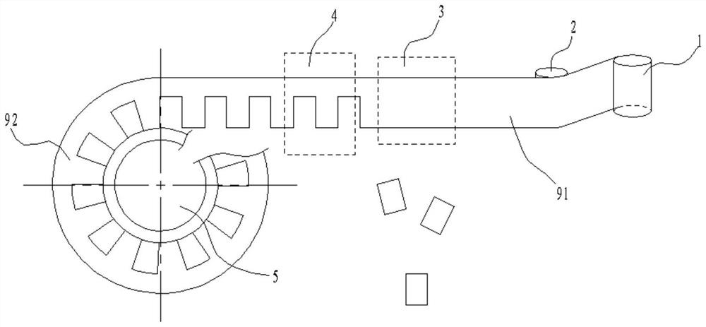
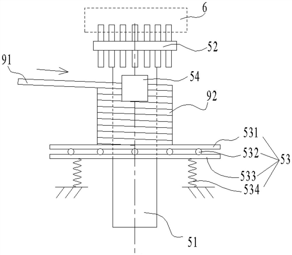
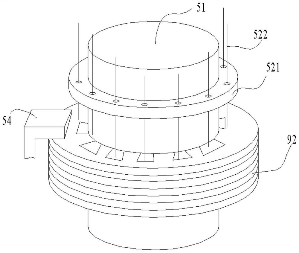
[0025] Such as figure 1 As shown, a motor iron core winding equipment is used to wind a steel strip 91 into an iron core 92. The winding equipment includes a silicon steel reel 1, a guide wheel 2, a stamping assembly 3, a winding assembly 5, and a silicon steel reel 1. Install the coiled steel strip 91, one end of the steel strip 91 is pulled out, bypasses the guide wheel 2 and pa...


PUM


Abstract

The invention discloses motor iron core winding equipment. A steel belt is wound into an iron core, and the winding equipment comprises a silicon steel winding drum, a guide wheel, a stamping assemblyand a winding assembly, wherein the coiled steel belt is arranged on the silicon steel winding drum, and one end of the steel belt is pulled out, bypasses the guide wheel, penetrates through the stamping assembly and then reaches the winding assembly; the winding assembly is used for winding a steel belt into a sheet spiral iron core, the guide wheel plays a role in guiding and supporting, and the stamping assembly is used for stamping a wire embedding groove in the steel belt. The winding assembly comprises a winding drum, a driving pin wheel, a tray and an extrusion inclined plane, the winding drum is vertically arranged, a rotary driver is arranged at the bottom of the winding drum, an iron core is wound around the outer cylindrical surface of the winding drum, and the driving pin wheel is detachably installed at the upper end of the winding drum, provided with a plug pin capable of extending downwards and inserted into an iron core wire embedding groove downwards; the bottom of the iron core is borne on the tray, the tray can be pressed downwards, and the extrusion slope is located at the position where the steel belt is wound into the iron core and extrudes the steel belt downwards by the distance of the thickness of the steel belt.

Description

technical field [0001] The invention relates to the technical field of iron core manufacturing, in particular to a motor iron core winding device. Background technique [0002] The motor iron core is an important part of various motors and generators, and is the main component of the motor cost. Because the motor accounts for a very high proportion in industrial production, the production of the iron core only needs to slightly increase the material utilization rate and yield. Can bring significant economic benefits. [0003] In traditional iron core processing, the shape of iron chips is punched out on the plate, and then stacked together and welded together. The material utilization rate of this method is very low, and a large amount of material is wasted as scrap; [0004] In the existing technology, more and more iron cores are manufactured by coiling process. The raw material is the steel strip coil on which the embedding groove has been punched. According to the diffe...

Claims


Application Information

Patent Timeline
Patent Type & Authority Applications(China)
IPC IPC(8): H02K15/00
CPCH02K15/00
Inventor 不公告发明人
Owner 张莉
Why Eureka
Try Eureka