Die cutting method convenient for detection

A die-cutting and die-cutting technology, applied in the field of die-cutting that is easy to detect, can solve the problems of reducing the yield rate, affecting product quality, lack of lubrication, etc., to reduce the generation of air bubbles, reduce the phenomenon of glue overflow, and reduce the defect rate.

Inactive Publication Date: 2021-02-23
东莞艾塔极新材料科技有限公司
View PDF5 Cites 2 Cited by
  • Summary
  • Abstract
  • Description
  • Claims
  • Application Information

AI Technical Summary

Problems solved by technology

[0003] The bonding process and die-cutting process are one of the most common processes in the touch screen manufacturing process. In the process of bonding OCA optical adhesive to each base layer, bubbles will inevitably appear. Due to the large number of intermediate products with problems, It is not suitable to be discarded directly. At this stage, it is generally time-consuming and labor-intensive to rework products with air bubbles. During the die-cutting process, due to inaccurate alignment, it is easy to make the size of each layer of colloid deviate from the error, so that the product is scrapped. If it is not found in time, it will affect the same batch. The quality of sub-products; the lack of lubrication between the tool and the tape during the die-cutting process will cause difficulties in the product and the tape falling off, reducing the yield rate, so a method can reduce air bubbles, and at the same time allow the staff to intuitively and timely find out the deviation error of the product shape and size , the process of improving product and tape release is currently lacking in the market

Method used


Image

  • Die cutting method convenient for detection

Examples


Embodiment 1

[0022] Example 1: Reference figure 1 , a kind of die-cutting method that is easy to detect is characterized in that, comprises the blanking mold that is used for this method, and described blanking mold comprises mold body and marking device, and described mold body has the same cutting tool as preset shape ;

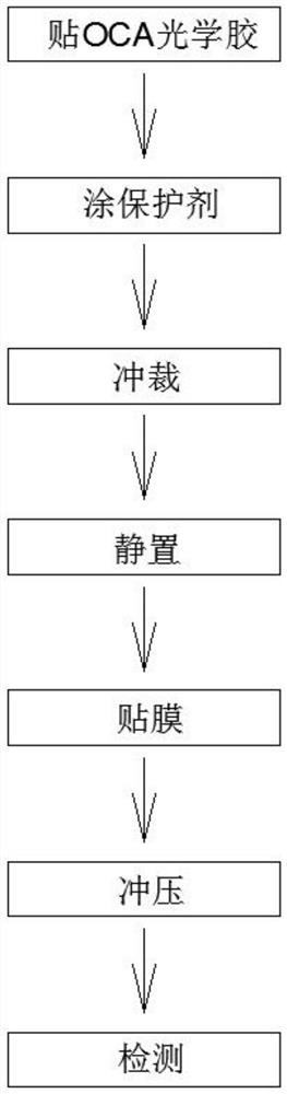
[0023] Steps include:

[0024] (1). Paste OCA optical glue, place OCA optical glue on the heavy release film, and stick them together by a laminating machine to form a composite film;

[0025] (2). Apply protective agent, and coat a layer of uniform degumming protective agent on the upper surface of the composite film;

[0026] (3). Punching, using a punching die to punch out the composite film, punching out the OCA optical adhesive layer into a plate with the same preset shape, and leaving a detection mark on the composite film through the marking device;

[0027] In this embodiment, the projection of the marking device on the composite film is outside the maximum d...

Embodiment 2

[0032] Embodiment 2: Different from Embodiment 1, in this embodiment, the detection of step (7) is judged by the optical detection device. Analyze and judge product images.


PUM


Abstract

The invention relates to a die cutting detection process. The die cutting detection process comprises the following steps that an OCA (Optically Clear Adhesive) is placed on a heavy release film, andthe OCA and the heavy release film are laminated together through a laminating machine to form a composite film; the upper surface of the composite film is coated with a layer of uniform degumming protective agent; the composite film is stamped by using a blanking die, an OCA layer is blanked into a proper shape, and a detection mark is left on the composite film through a marking device; the composite film obtained in the previous step is stood for 15 minutes; a light release film is put on the upper surface of the composite film, and the light release film and the composite film are laminated through the laminating machine to form a finished film; the finished film is stamped by using a forming die, and a product is stamped and formed; and the machined product is detected; The degummingprotective agent is added in the film laminating process, bubbles are reduced, and the separation of the product and an adhesive tape is facilitated; and the die cutting effect of the product is directly judged by observing whether the product has the detection mark or not, other equipment is not needed for measurement, and defective products can be directly found.

Description

technical field [0001] The invention relates to the fields of a die-cutting method and a mobile phone film processing field, in particular to a die-cutting method which is convenient for detection. Background technique [0002] OCA (Optically Clear Adhesive) optical adhesive is one of the raw materials of the touch screen. The optical acrylic pressure-sensitive adhesive is made without a substrate, and then a layer of optical release film is attached to the upper and lower bottom layers to make a double-sided adhesive tape. A double-sided laminating tape without a matrix material, which has the advantages of high cleanliness, high light transmittance, low haze, high adhesion, no crystal point, no bubbles, water resistance, high temperature resistance, UV resistance, etc., and its thickness High uniformity and flatness, close to glass, PC, PMMA refractive index, long-term use will not cause problems such as yellowing, aging, fogging, detachment from the adhered surface, and b...

Claims


Application Information

Patent Timeline
Patent Type & Authority Applications(China)
IPC IPC(8): B26F1/38B26D7/27B29C63/02C09J7/40
CPCB26F1/38B26D7/27B29C63/02C09J7/401
Inventor 周智强
Owner 东莞艾塔极新材料科技有限公司
Why Eureka
Try Eureka